Introduction
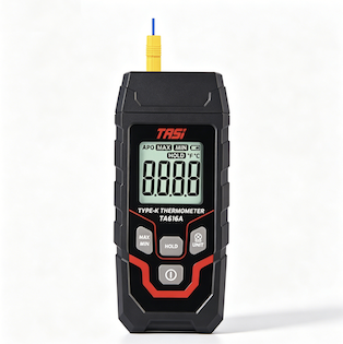
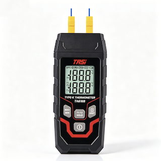
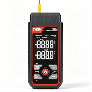
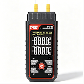
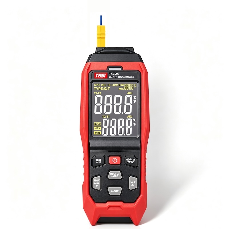
● When measuring temperature with a thermocouple, two apparently identical measurement setups can still produce different results. The reason is that the displayed temperature depends on the entire measurement system rather than on the thermocouple probe alone.
● A complete thermocouple measurement chain typically includes the measuring junction, thermocouple or extension wires, connectors, cold-junction compensation circuitry, the measuring instrument, and the installation environment.
● Any deviation in one of these elements can affect the final temperature reading. For this reason, thermocouple error analysis should consider the entire measurement chain rather than only the specified accuracy of the probe or instrument.
Key Takeaways
● The thermocouple itself has a specified tolerance and is one of the fundamental sources of measurement error.
● Cold-junction compensation accuracy directly affects the calculated temperature.
● Incorrect thermocouple type selection, reversed polarity, or incompatible extension wires can cause significant errors.
● Probe position, insertion depth, heat conduction, and contact quality are among the most frequently overlooked error sources in practical applications.
● When temperature changes rapidly, thermocouple response time can cause the indicated temperature to lag behind the actual temperature.
● Electromagnetic interference, ambient temperature variation, sensor aging, and measuring instrument error must also be considered.
● Overall system accuracy should be evaluated using the thermocouple, instrument, cold-junction compensation, wiring, and application conditions together.
Thermocouple Tolerance
● A thermocouple is made from two dissimilar metals or alloys whose thermoelectric voltage varies with temperature. In practice, actual thermocouple materials cannot exactly reproduce the ideal reference thermoelectric characteristics, so a certain amount of deviation is unavoidable.
● Different thermocouple types and tolerance classes have different permissible deviations. K, J, T, and E thermocouples, for example, use different material combinations and therefore have different thermoelectric characteristics, usable temperature ranges, and tolerance limits.
● Even if the measuring instrument itself were perfectly accurate, a deviation in the thermoelectric voltage produced by the thermocouple would still result in a temperature error.
● Applications requiring higher accuracy should therefore consider both the thermocouple type and the appropriate tolerance class for the intended temperature range.
Cold-Junction Compensation Error
● Thermocouple voltage depends on the temperature difference between the measuring junction and the reference junction rather than on the measuring-junction temperature alone. Thermocouple thermometers therefore use cold-junction compensation (CJC) to determine the terminal temperature and calculate the actual measured temperature.
● If the cold-junction temperature sensor is inaccurate, or if a significant temperature gradient exists around the input terminals, the compensation result may be incorrect.
● This can occur, for example, when an instrument is moved from a cold environment into a warm room, exposed to direct sunlight, or operated near hot equipment before its internal temperature has stabilized.
● After a significant change in ambient temperature, sufficient time should therefore be allowed for the instrument and its input terminals to reach thermal stability.
Measuring Instrument Error
● Thermocouples typically generate signals in the millivolt range. The measuring instrument must measure this low-level voltage and then convert it into temperature using the characteristic curve for the selected thermocouple type.
● Input circuit accuracy, analog-to-digital conversion, cold-junction compensation, linearization algorithms, and internal calibration can all influence the final reading.
● The specified accuracy of a thermocouple thermometer and the accuracy or tolerance of the connected probe are therefore two different parameters.
● Overall measurement performance normally requires both instrument error and thermocouple error to be considered rather than relying on either specification alone.
Incorrect Thermocouple Type Setting
● Different thermocouple types use different metal combinations and therefore generate different thermoelectric voltages at the same temperature.
● If a K-type thermocouple is connected while the instrument is configured for J, T, or another type, the instrument applies the wrong voltage-to-temperature relationship and may produce a substantial error.
● At some temperatures, the output voltages of different thermocouple types may be relatively close, so the incorrect setting may not immediately appear abnormal. The error can, however, increase significantly as temperature changes.
● With multi-input thermocouple instruments, always verify that the selected thermocouple type matches the connected sensor.
Reversed Polarity
● Thermocouples have positive and negative conductors. If the polarity is reversed, the direction of the thermoelectric voltage is also reversed.
● Depending on the measurement conditions, reversed polarity may cause readings that are significantly lower than expected, change in the wrong direction, or even decrease as the actual temperature rises.
● Thermocouple wire color coding varies between standards and regions, so conductor color alone should not always be used to determine polarity.
● The more reliable approach is to verify polarity from the thermocouple type, conductor material, connector markings, or the manufacturer's documentation.
Extension Wire and Connector Errors
● When the distance between the thermocouple and the measuring instrument must be increased, thermocouple extension wire or compensating cable that is suitable for the thermocouple type should normally be used.
● Connecting ordinary copper wire directly into the thermocouple measurement circuit, or using the wrong type of extension cable, can introduce additional thermoelectric junctions.
● If these junctions are at different temperatures, additional thermoelectric voltages may be generated and appear as temperature error.
● Connectors should also be compatible with the thermocouple type. Loose, oxidized, contaminated, or unstable connections can cause fluctuating readings and increase measurement uncertainty.
Incorrect Probe Position
● A thermocouple actually measures the temperature of its measuring junction. Only when the junction reaches sufficient thermal equilibrium with the target can its temperature be considered representative of the target temperature.
● If the measurement point is located in a strong temperature gradient, such as near a heater, cooling outlet, equipment wall, or edge of a heat source, measurements taken at different positions may differ considerably.
● In pipes, furnaces, tanks, or machinery, an incorrectly positioned probe may fail to represent the region that actually needs to be monitored even when the thermocouple and instrument themselves are operating correctly.
● Probe location is therefore an important source of application-related measurement error.
Insufficient Insertion Depth and Heat-Conduction Error
● When a sheathed thermocouple measures the temperature of a gas, liquid, or internal process, heat is transferred not only to the sensing end but also along the metallic sheath.
● If the insertion depth is insufficient, the surrounding environment outside the process may conduct heat through the probe stem and prevent the measuring junction from reaching the true process temperature.
● The influence becomes more important when large temperature differences exist and is also affected by probe diameter, sheath material, and installation design.
● In applications with strong temperature gradients, sufficient insertion depth should therefore be provided according to probe construction and process conditions.
Surface Contact Measurement Error
● When a thermocouple is used to measure surface temperature, the quality of contact between the measuring junction and the target surface is critical.
● Air gaps, insufficient contact pressure, surface roughness, or an oversized sensing tip may cause the thermocouple to be influenced simultaneously by the surface and the surrounding air.
● These effects become more significant when there is a large temperature difference between the target surface and the environment.
● For surface temperature measurement, the sensing tip should maintain stable, effective contact with the target, and a probe specifically designed for surface measurement should be selected where appropriate.
Dynamic Error Caused by Response Time
● A thermocouple requires a finite amount of time to respond to a temperature change. If the target temperature rises or falls rapidly, the displayed value does not immediately reach the new actual temperature.
● This difference caused by the thermal inertia of the sensor is referred to as dynamic measurement error.
● Response speed depends on the measuring-junction construction, probe diameter, sheath thickness, medium velocity, mounting method, and heat-transfer conditions.
● If the thermocouple responds too slowly in a rapidly changing process, it may fail to capture short-duration temperature peaks, minimum values, or rapid thermal transitions.
Ambient Temperature and Thermal Radiation
● A thermocouple probe can exchange heat not only with the target but also with the surrounding air and nearby hot or cold surfaces.
● In a high-temperature furnace, for example, the thermocouple may be influenced by radiation from the furnace walls. During low-temperature surface measurements, warmer surrounding air can also affect the sensing junction.
● If the measuring junction does not achieve the intended thermal relationship with the target, the surrounding thermal environment may shift its temperature away from the value that is actually being measured.
● For higher-accuracy applications, shielding, insertion method, probe construction, and mounting location should be considered in relation to the surrounding thermal environment.
Electromagnetic Interference and Grounding
● Thermocouple signals are typically only a few millivolts or tens of millivolts, making them relatively susceptible to electrical noise in industrial environments.
● If thermocouple cables are routed near variable-frequency drives, motors, power cables, relays, high-power heaters, or other sources of electromagnetic interference, unwanted signals can couple into the measurement circuit and cause unstable temperature readings.
● Improper grounding, ground loops, or incorrect cable-shield termination can also increase noise and measurement instability.
● Thermocouple signal cables should therefore be routed carefully, avoiding long parallel runs with power cables where possible, and appropriate shielding and grounding practices should be used for the installation.
Thermocouple Aging and Material Drift
● Long-term exposure to high temperature, oxidation, corrosion, or contamination can alter the composition and microstructure of thermocouple materials and gradually change their thermoelectric properties.
● This change is commonly referred to as drift and is an important source of error in thermocouples used over long periods.
● The higher the operating temperature, the longer the exposure time, and the more aggressive the environment, the greater the potential for aging effects.
● Oxidation, corrosion, mechanical damage, and contamination can also alter the thermoelectric output.
● In critical or continuously operated processes, thermocouples should be periodically inspected, verified, or calibrated to confirm that they still meet the required performance.
Calibration and Long-Term Measurement Stability
● Even if the thermocouple and measuring instrument meet their original accuracy specifications, their performance can change over time because of material aging, electronic drift, mechanical shock, or environmental exposure.
● For general trend monitoring, a basic functional check may be sufficient. Quality-control processes, laboratory measurements, and critical industrial applications may require a defined schedule for calibration or performance verification.
● Calibration is useful not only for determining current measurement error but also for identifying long-term drift in the thermocouple or instrument.
How Should Total Thermocouple Measurement Error Be Understood?
● Actual temperature measurement error is normally the combined effect of several contributors. A measurement system may simultaneously include thermocouple tolerance, instrument error, cold-junction compensation error, and installation-related error.
● If a thermocouple thermometer is specified with an instrument accuracy of ±0.5°C, this does not automatically mean that the total system accuracy is ±0.5°C because the connected thermocouple has its own tolerance.
● Likewise, even a high-accuracy thermocouple connected to a high-accuracy instrument may still produce a substantial application error if the probe is incorrectly positioned, insufficiently inserted, or poorly coupled to the target surface.
● For high-accuracy applications, a complete error budget or measurement uncertainty assessment should consider the sensor, instrument, cold-junction compensation, wiring, and practical installation conditions.
How Can Thermocouple Measurement Error Be Reduced?
● Select the thermocouple type and tolerance class according to the required temperature range and accuracy.
● Verify that the connected thermocouple type matches the instrument setting.
● Connect positive and negative thermocouple conductors correctly.
● Use compatible extension wire, compensating cable, and connectors.
● After major ambient temperature changes, allow the instrument and terminals to reach thermal stability.
● Select a probe construction, diameter, and response time appropriate to the target and process.
● Ensure suitable measurement location, insertion depth, and surface contact.
● Reduce electromagnetic interference from power wiring, variable-frequency drives, motors, and similar equipment.
● Periodically inspect the thermocouple for oxidation, corrosion, mechanical damage, and significant drift.
● For critical applications, perform regular calibration or performance verification and evaluate accuracy for the complete measurement system rather than for a single component.
FAQ
● Is thermocouple measurement error mainly caused by the probe?
Not necessarily. Probe tolerance is only one part of the total measurement error. Cold-junction compensation, instrument accuracy, extension wiring, installation position, heat conduction, response time, and the operating environment can all influence the result.
● If the thermometer accuracy is ±0.5°C, is the actual temperature measurement error also ±0.5°C?
Usually not. If ±0.5°C refers only to the instrument, the thermocouple tolerance, cold-junction compensation error, and application-related factors must also be considered.
● Why does the same thermocouple show different temperatures at different positions?
The target may have a real temperature gradient. A thermocouple measures the temperature at its measuring junction, so changing the measurement location can produce a different reading.
● Can ordinary copper wire be used to extend a thermocouple?
It is generally not recommended for the thermocouple measurement section. A compatible thermocouple extension or compensating cable should be used because inappropriate conductor materials can create additional thermoelectric junctions and measurement error.
● Can thermocouple accuracy deteriorate over time?
Yes. High temperature, oxidation, corrosion, contamination, and mechanical damage can alter the thermoelectric characteristics and cause long-term drift.
● Does a fluctuating reading always mean the thermocouple is faulty?
No. Loose connections, electromagnetic interference, grounding problems, damaged wiring, unstable contact, or actual temperature fluctuations can also cause unstable readings.
● How can I determine whether the error comes from the thermocouple or the instrument?
A known reference thermocouple, calibrated temperature source, or suitable calibration equipment can be used to evaluate the probe and instrument separately. For higher-accuracy applications, both components and the complete measurement chain should be verified.
Summary
● Thermocouple measurement error is not determined by a single specification. It results from the combined effects of the thermocouple, cold-junction compensation, measuring instrument, wiring, installation, and surrounding environment.
● Thermocouple tolerance and instrument accuracy are relatively easy to quantify, while installation position, insertion depth, surface contact, response time, and heat conduction are often more easily overlooked in practical measurements.
● For routine temperature monitoring, thermocouple type, polarity, wiring, and installation should first be confirmed. Process control, laboratory testing, and other high-accuracy applications should additionally consider a complete error budget, calibration status, and long-term drift.
● Understanding all relevant error sources is more important than focusing only on a higher instrument accuracy specification. Reliable temperature measurement requires evaluating the entire measurement system.