Introduction
A thermocouple does not measure temperature by detecting a change in electrical resistance. Instead, it generates a small thermoelectric voltage from two dissimilar conductors. For this reason, correct conductor pairing and polarity must be maintained from the thermocouple probe through the connector and extension or compensating cable to the measuring instrument.
Thermocouple connectors are normally marked with clear “+” and “−” polarity symbols. Many designs also use different pin sizes, connector colors or wire color codes to help identify polarity. However, color conventions vary between standards and manufacturers, so wire color alone should not be used as the sole method of identification.
Correctly identifying thermocouple connector polarity is a basic requirement for reliable temperature measurement.
Key Points
● The “+” and “−” markings on a thermocouple connector should be the primary reference for polarity identification;
● Many polarized thermocouple plugs use different pin dimensions to reduce the risk of reverse connection;
● Thermocouple wire colors vary between standards such as ANSI/ASTM and IEC, so color must always be interpreted within the correct standard;
● K, J, T and E thermocouples use different positive and negative conductor materials;
● Reversed polarity changes the direction of the thermoelectric voltage and can produce clearly incorrect temperature readings;
● When replacing a connector, both polarity and thermocouple type must be matched correctly.
Why Do Thermocouple Connectors Have Positive and Negative Polarity?
A thermocouple consists of two dissimilar metal or alloy conductors joined at the measuring junction. When a temperature difference exists between the measuring junction and the reference junction, a thermoelectric voltage is generated.
This voltage is typically in the microvolt-to-millivolt range, but it has a defined polarity. Thermocouple circuits therefore have a positive and a negative conductor.
For example, a Type K thermocouple typically uses Chromel as the positive conductor and Alumel as the negative conductor. The temperature instrument interprets the measured voltage according to the standardized voltage-to-temperature relationship for Type K thermocouples.
If the positive and negative conductors are reversed at the connector, the polarity of the signal entering the instrument is also reversed. As a result, the displayed temperature may change in the opposite direction to the actual temperature.
Correct polarity must therefore be maintained throughout the complete thermocouple measurement circuit.
The Most Direct Method: Check the “+” and “−” Markings
Proper thermocouple connectors normally have polarity symbols marked on the housing or near the terminals:
● “+” indicates the positive terminal;
● “−” indicates the negative terminal.
When installing the thermocouple wires, connect the positive conductor to the “+” terminal and the negative conductor to the “−” terminal.
This is the simplest and generally the most reliable identification method.
If the markings have become worn, damaged or unreadable, polarity should be confirmed using additional information such as pin dimensions, wire color coding and thermocouple conductor materials rather than relying on guesswork.
Identifying Polarity by Connector Pin Size
Many standard thermocouple connectors use a polarized mechanical design. The positive and negative pins are different in size so that the plug can normally be inserted only in the correct orientation.
In many common connector designs:
● The positive pin is narrower or smaller;
● The negative pin is wider or larger.
This mechanical arrangement helps prevent reverse insertion into a matching socket.
If the “+” and “−” markings are no longer visible, the difference in pin width can therefore provide a useful indication of polarity.
However, connector designs vary by series, size and manufacturer. Pin dimensions should therefore be treated as a secondary identification method. The connector markings and manufacturer documentation should remain the primary references.
Can Wire Color Be Used to Identify Polarity?
Yes, but only as a supporting method.
Thermocouple and compensating cables commonly use color coding to identify thermocouple type and conductor polarity. However, several color-code systems are used internationally, and ANSI/ASTM and IEC conventions are not identical.
For example, under some ANSI/ASTM color conventions, the negative conductor of many common thermocouple types is red. Under IEC conventions, the negative conductor is commonly white.
Therefore, a red wire cannot automatically be interpreted using an IEC-based assumption, and a white wire cannot automatically be interpreted using an ANSI/ASTM-based assumption.
A more reliable procedure is:
● Confirm the thermocouple type;
● Identify the applicable wire color standard;
● Check the “+” and “−” markings on the connector;
● Refer to the cable or connector manufacturer’s specifications when necessary.
Wire color is useful for quick identification, but it should not be the only basis for determining polarity.
What Are the Positive and Negative Materials of Common Thermocouple Types?
Different thermocouple types use different conductor combinations, so their positive and negative materials also differ.
Common examples include:
● Type K: positive conductor typically Chromel; negative conductor typically Alumel;
● Type J: positive conductor typically iron; negative conductor typically Constantan;
● Type T: positive conductor typically copper; negative conductor typically Constantan;
● Type E: positive conductor typically Chromel; negative conductor typically Constantan.
When no usable color or polarity marking is available, conductor material can sometimes provide an additional clue.
For example, the positive conductor of a Type J thermocouple is iron and can show noticeable magnetic attraction. The positive conductor of a Type T thermocouple is copper and is usually easier to identify visually.
However, many thermocouple alloys cannot be identified reliably by appearance alone. Material appearance should therefore not be used as the sole method for field wiring.
How to Identify the Polarity of a Type K Thermocouple Connector
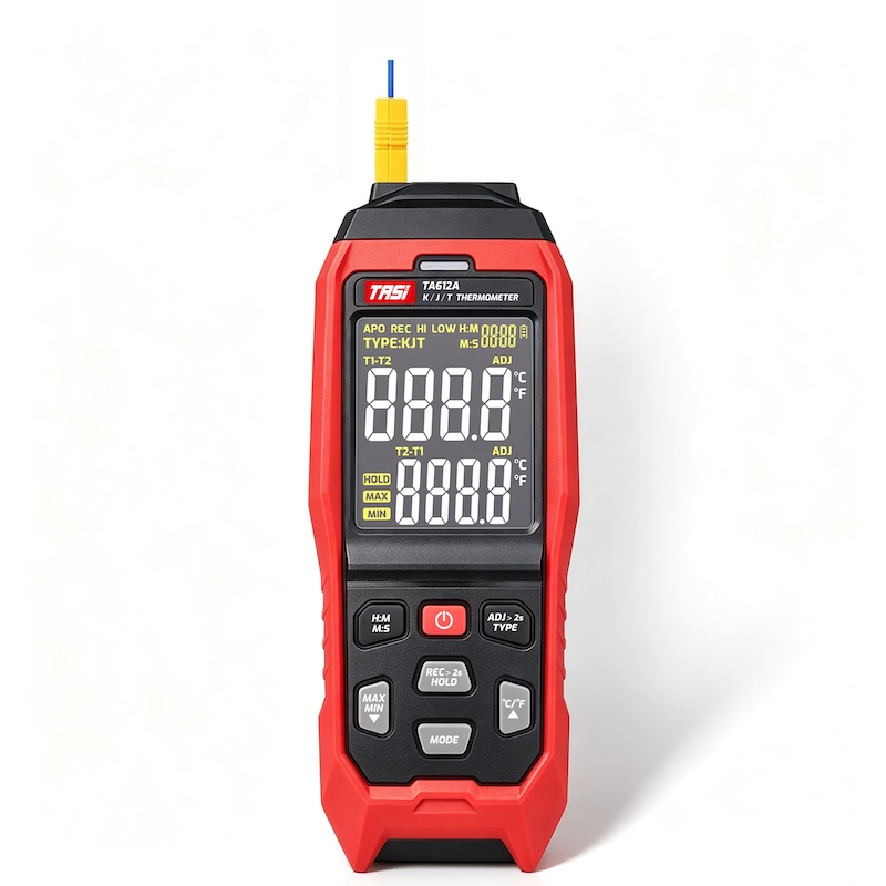
Type K is one of the most widely used thermocouple types in handheld thermometers, industrial temperature instruments and data loggers.
The typical conductor combination is:
● Positive: Chromel, a nickel-chromium alloy;
● Negative: Alumel, a nickel-based alloy containing aluminium.
When wiring a Type K connector, the Chromel conductor should be connected to the “+” terminal and the Alumel conductor to the “−” terminal.
Standard Type K plugs normally indicate polarity through “+” and “−” symbols and a polarized pin arrangement.
During repair or connector replacement, it is good practice to record the original conductor positions before removing the old connector. This avoids confusion if the wire colors are faded or the conductor surfaces have oxidized.
What Happens If a Thermocouple Connector Is Wired in Reverse?
If the positive and negative conductors are reversed, the polarity of the thermoelectric signal relative to the measuring instrument is reversed.
Possible symptoms include:
● The measured object becomes hotter while the displayed temperature decreases;
● The indicated temperature is clearly inconsistent with the actual process temperature;
● Unusually low or negative readings may appear under certain conditions;
● A comparison with a correctly connected thermocouple shows a significant difference.
For example, if a thermocouple probe is placed in an environment well above room temperature and the displayed value moves rapidly downward instead of upward, connector polarity should be checked.
However, an abnormal reading does not always indicate reversed polarity. Incorrect thermocouple type selection, cold-junction compensation errors, incompatible connector materials or damaged wiring can produce similar symptoms.
Can Connector Color Identify the Thermocouple Type?
Many thermocouple connectors use housing colors to distinguish between thermocouple types. Type K, J, T and E connectors may therefore have different colors.
This can help users quickly identify probes in laboratories, HVAC applications, industrial maintenance, equipment commissioning and multichannel temperature measurement systems.
However, connector colors may vary according to regional standards and manufacturer practices.
For this reason, the connector type marking should always be checked. Typical markings include:
● K;
● J;
● T;
● E.
A connector marked “K” is intended for a Type K thermocouple circuit. It should not be substituted for a Type J or Type T connector simply because the mechanical dimensions appear compatible.
Why Must the Connector Type Match the Thermocouple Type?
A thermocouple connector is more than a mechanical plug.
The conductive components of a purpose-designed thermocouple connector are normally made from materials selected to be compatible with the corresponding thermocouple type. This helps minimize additional parasitic thermoelectric voltages at the connection point.
Two connectors may therefore look identical while using different internal materials.
Using an incompatible connector in a Type K circuit, for example, may introduce additional measurement error when a temperature gradient exists across the connector.
The basic principle is:
● Type K thermocouple → Type K connector;
● Type J thermocouple → Type J connector;
● Type T thermocouple → Type T connector;
● Type E thermocouple → Type E connector.
Correct polarity must also be maintained throughout the connection chain.
How Should a Thermocouple Connector Be Wired When Replaced?
When replacing a thermocouple plug or socket, use the following sequence:
● Confirm whether the probe is Type K, J, T, E or another thermocouple type;
● Select a connector designed for that thermocouple type;
● Locate the “+” and “−” markings on the connector terminals;
● Identify the polarity of the two conductors using the correct material or color-code information;
● Connect the positive conductor to “+” and the negative conductor to “−”;
● Secure the conductors and check that there are no loose terminals or short circuits;
● Connect the probe to the instrument and verify operation using a known or stable temperature source.
If the wire color standard cannot be confirmed, the probe specification should be checked rather than relying on color alone.
How Can You Quickly Check Whether a Thermocouple Is Reversed?
A simple functional check can be carried out in the field.
Connect the thermocouple to an instrument configured for the correct thermocouple type. Then warm the measuring junction by holding it in your hand or placing it against a stable object that is warmer than the surrounding environment.
Under normal conditions, the indicated temperature should increase as the probe warms.
If the probe is clearly being heated while the displayed temperature continues to decrease, check:
● Whether the thermocouple connector polarity is reversed;
● Whether an extension or compensating cable has been connected in reverse;
● Whether the instrument is configured for the wrong thermocouple type;
● Whether polarity has been crossed at an intermediate terminal.
This method is useful for initial troubleshooting, but it does not replace formal calibration or metrological verification.
Why Are Polarity Errors More Common in Multi-Section Thermocouple Circuits?
More complex temperature measurement systems may contain several connection points, for example:
Thermocouple probe → thermocouple plug → extension or compensating cable → terminal block → thermometer or data acquisition system.
If polarity is crossed at any one of these points, measurement errors can occur.
For long-distance industrial installations, it is therefore not sufficient to inspect only the probe connector. The entire signal path should be checked section by section.
This is particularly important during equipment maintenance, replacement of compensating cable, control-panel modifications or terminal rewiring. Compatible thermocouple materials and correct polarity should be maintained throughout the complete circuit.
FAQ
Will reversing thermocouple connector polarity damage the thermometer?
In most cases, no. A thermocouple generates only a very small thermoelectric voltage, so reversing the positive and negative conductors will normally cause incorrect readings rather than damage a properly designed thermocouple thermometer. The wiring should nevertheless be corrected as soon as an abnormal response is detected.
Is the larger thermocouple connector pin always negative?
Many polarized thermocouple connectors use a larger negative pin and a smaller positive pin, but this should not be treated as a universal rule for every connector design. Always check the polarity markings and the manufacturer’s technical information.
Which wire is positive on a Type K thermocouple?
The positive conductor is typically Chromel, while the negative conductor is Alumel. If color coding is used for identification, the applicable wiring standard must first be confirmed.
Why should thermocouple polarity not be identified by wire color alone?
Because ANSI/ASTM, IEC and other systems may use different color conventions. Wire color should always be interpreted together with the thermocouple type, connector markings and applicable standard.
Can an ordinary copper connector replace a thermocouple connector?
For accurate thermocouple measurement, ordinary connectors should not be substituted arbitrarily for dedicated thermocouple connectors. Dissimilar materials at the connection point can generate additional thermoelectric voltages when temperature gradients are present.
If a thermocouple plug fits the socket, does that mean it is the correct type?
No. Different thermocouple connector types may use similar mechanical dimensions. Mechanical compatibility does not guarantee that the internal materials are suitable. Always check the K, J, T, E or other thermocouple type marking.
Conclusion
Correct identification of thermocouple connector polarity is a simple but essential part of reliable temperature measurement.
The most dependable method is to use the “+” and “−” markings on the connector and confirm that the connector type matches the thermocouple type. Pin dimensions, wire colors and conductor materials can provide useful secondary information, but they should not be used independently of the applicable standard or manufacturer specifications.
When installing or replacing a thermocouple connector, follow one fundamental principle: match the thermocouple type, maintain compatible materials and preserve polarity throughout the complete measurement circuit.
When the probe, connector, extension or compensating cable and instrument input are correctly matched, wiring-related measurement errors can be minimized and a reliable thermoelectric signal can be maintained.