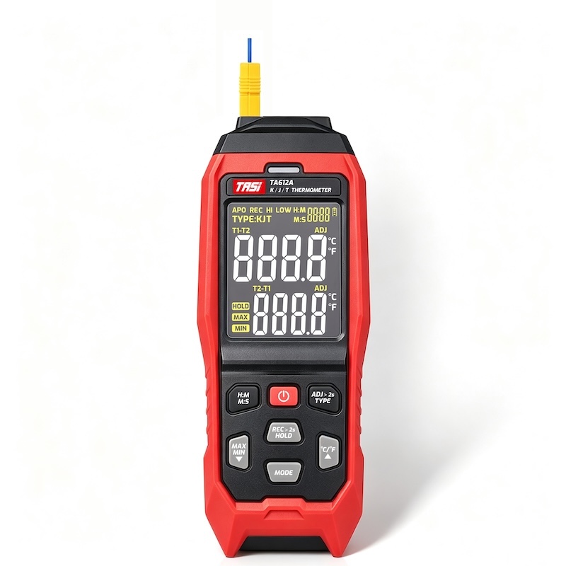
Introduction
Thermocouples differ fundamentally from resistance-based temperature sensors such as RTDs and thermistors. Instead of producing a change in resistance, a thermocouple generates a small thermoelectric voltage as a result of the temperature difference within a circuit made from two dissimilar conductor materials.
For this reason, the conductor materials, connections, and temperature distribution along the path between the thermocouple measuring junction and the temperature instrument can all affect the final measurement.
Thermocouple wire should therefore not be treated as ordinary signal cable. If the original cable becomes damaged, needs to be extended, or is rewired using ordinary copper cable or an incorrect thermocouple cable type, additional thermoelectric junctions may be introduced. This can cause the displayed temperature to read high or low, or to drift as the ambient temperature changes.
Key Takeaways
● Thermocouple wire is part of the temperature measurement circuit, not merely an electrical connection;
● K, J, T, E, and other thermocouple types use different alloy combinations and have different temperature-to-EMF characteristics;
● Using conductors with incorrect thermoelectric properties can introduce additional voltages and measurement errors;
● Thermocouple type and polarity must both be maintained when replacing or reconnecting wiring;
● Thermocouple extension wire or compensating cable matched to the thermocouple type should be used when extending the circuit;
● Insulation material, operating temperature, conductor size, mechanical conditions, and the installation environment must also be considered.
Why Is Thermocouple Wire Different from Ordinary Electrical Wire?
A thermocouple consists of two dissimilar metals or alloys. A K-type thermocouple, for example, commonly uses nickel-chromium and nickel-aluminium-based alloys. When a temperature difference exists between the measuring junction and the reference junction, a thermoelectric voltage is generated.
A temperature instrument measures this voltage, typically in the millivolt range, and converts it into a temperature using the characteristic EMF-versus-temperature relationship of the selected thermocouple type.
The conductor materials in the thermocouple circuit therefore have defined thermoelectric properties. Introducing another metal into the circuit creates additional dissimilar-metal junctions.
In an ordinary electrical circuit, a copper conductor is generally selected according to resistance, current-carrying capacity, insulation, and mechanical requirements. In a thermocouple circuit, the thermoelectric behaviour of the conductor must also be considered. This is the fundamental reason thermocouple wiring cannot be replaced arbitrarily.
Why Does Each Thermocouple Type Require the Correct Wire?
K, J, T, E, and other thermocouple types are manufactured from different combinations of conductor materials. Each type therefore has its own thermoelectric voltage characteristic.
Even at exactly the same temperature, K-, J-, and T-type thermocouples do not generate identical thermoelectric voltages. The measuring instrument must use the correct EMF-to-temperature relationship for the selected sensor type.
If a K-type thermocouple circuit is extended with J-type, T-type, or another cable having different thermoelectric properties, the characteristics of the overall measurement circuit can be altered.
Before replacing thermocouple wiring, the original thermocouple type should therefore be identified. Selection should not be based only on conductor size, insulation colour, or physical appearance.
What Happens If Ordinary Copper Wire Is Used?
This is a common thermocouple installation issue.
If ordinary copper wire is inserted between the thermocouple and the measuring instrument, new junctions are created between the thermocouple alloys and the copper conductors.
According to the law of intermediate metals, an additional metal does not affect the total thermoelectric voltage if the two newly created junctions are maintained at exactly the same temperature.
In practical industrial installations, however, it is often difficult to ensure that both junctions remain at identical temperatures.
For example, one connection may be located close to hot process equipment while the other is inside a cooler control cabinet. The temperature difference between these points can generate an unwanted thermoelectric contribution.
Ordinary copper wire should therefore not be considered a universal solution for extending a thermocouple circuit, particularly where significant temperature gradients, long cable runs, or higher measurement accuracy are involved.
Why Can Incorrect Wire Cause Temperature Measurement Errors?
When an incorrect conductor material is introduced into a thermocouple circuit, the primary problem is not simply electrical conductivity. The more important issue is the possibility of generating additional thermoelectric voltage.
Consider a thermocouple circuit consisting of materials A and B. If a third material C is introduced, new A-C and B-C junctions are formed.
If these junctions are at different temperatures, additional thermoelectric voltages may be generated. The temperature instrument cannot distinguish these voltages from those generated by the actual sensing junction. It therefore converts the total measured voltage according to the thermocouple type selected in the instrument.
The displayed temperature can consequently deviate from the actual temperature at the measuring junction.
This type of error may also vary with ambient temperature. A system can therefore appear correct during start-up but develop a noticeable offset as nearby equipment heats up.
Why Must Thermocouple Polarity Be Correct?
Correct thermocouple wiring depends not only on conductor material but also on polarity.
The two thermocouple conductors have defined positive and negative polarities. Reversing them changes the direction of the thermoelectric voltage.
In some installations this may result in an obviously incorrect temperature. In others, because of cold-junction compensation and ambient temperature conditions, the reading may not simply become negative. Instead, the instrument may display a temperature that appears plausible but is incorrect.
When servicing or rewiring a thermocouple circuit, verify:
● The correct thermocouple type;
● Correct positive and negative polarity;
● Thermocouple-compatible terminals or connectors;
● The absence of unintended dissimilar-metal connections in areas with temperature differences.
What Is Thermocouple Extension Wire?
Thermocouple extension wire is used to increase the distance between a thermocouple and the measuring instrument.
Extension-grade wire is designed to provide the same or closely matched thermoelectric characteristics as the corresponding thermocouple over a specified temperature range.
For many common base-metal thermocouples, extension wire may use alloy systems corresponding to those of the thermocouple itself. However, its manufacturing tolerance, permissible temperature range, construction, and intended application may differ from wire designed for use directly at the sensing junction.
The term “extension wire” therefore does not mean that every thermocouple extension cable is interchangeable. K-type thermocouples require compatible K-type extension wire, while J-, T-, and E-type thermocouples require their corresponding cable types.
What Is Thermocouple Compensating Cable?
Compensating cable is also used to extend the electrical connection between a thermocouple and a temperature instrument, but it is not necessarily identical to extension-grade wire.
Some compensating cables use conductor alloys that are different from those of the original thermocouple. These materials are selected to provide similar thermoelectric characteristics within a specified temperature range and tolerance.
This approach is particularly useful for certain thermocouple systems that use expensive or specialised conductor materials.
Compensating cable is normally specified for a limited operating temperature range. It should therefore not be installed in locations exceeding its rated temperature, nor should it be used as the actual sensing element unless specifically designed for that purpose.
Both extension wire and compensating cable are intended to extend thermocouple signals, but their conductor materials, temperature limitations, and accuracy characteristics can differ. Selection must be based on the thermocouple type and the cable specification.
Can Thermocouple Wires Be Interchanged If the Colours Are the Same?
No. Colour alone is not a reliable basis for interchangeability.
Thermocouple colour codes can differ between standards, regions, and manufacturers. Two cables with similar colours may therefore contain completely different conductor alloys.
The outer sheath colour and the colours used to identify the positive and negative conductors are also separate identification systems. Relying only on the outer insulation can lead to incorrect cable selection.
The more reliable approach is to check the thermocouple type designation, cable marking, technical datasheet, and manufacturer wiring information.
If the original cable type cannot be positively identified, replacing it solely because another cable “looks the same” is not recommended.
What Other Factors Should Be Considered?
Correct thermocouple wire selection involves more than matching the conductor alloy.
● Insulation material: PVC, PTFE, fibreglass, and other insulation systems have different temperature and environmental capabilities;
● Operating temperature: The conductor may withstand a higher temperature than the insulation surrounding it;
● Mechanical conditions: Applications involving vibration, repeated bending, moving equipment, or cable carriers require suitable flexibility and mechanical durability;
● Chemical environment: Oil, moisture, chemicals, and corrosive atmospheres can damage insulation or conductors;
● Electromagnetic interference: Installations near motors, variable-frequency drives, and high-power equipment may require screened cable and appropriate routing;
● Conductor size and cable length: Thermocouple measurement is primarily based on thermoelectric voltage rather than circuit resistance, but very long or very small conductors, poor connections, and excessive loop resistance can reduce noise immunity or affect certain instrument functions such as open-sensor detection.
A suitable replacement cable must therefore match both the thermocouple type and the electrical, thermal, mechanical, and environmental requirements of the installation.
How Should Damaged Thermocouple Wire Be Replaced?
Before replacing the cable, identify the thermocouple type, such as K, J, T, or E, and determine whether the existing connection uses thermocouple-grade wire, extension wire, or compensating cable.
The replacement should match the thermocouple type and should also be checked for correct polarity, conductor material, insulation, permitted temperature range, and suitability for the installation environment.
Where possible, use terminals and thermocouple connectors designed for the corresponding thermocouple type to minimise unwanted dissimilar-metal junctions in areas where temperature gradients may occur.
After rewiring, confirm that the temperature instrument is configured for the same thermocouple type as the sensor. Where measurement accuracy is important, verify the complete system using a known temperature point, a calibrated temperature source, or a suitable reference thermometer.
Checking electrical continuity alone is not sufficient for a precision thermocouple measurement system. The thermoelectric integrity of the entire measurement chain must also be maintained.
What Are the Signs of Incorrect Thermocouple Wiring?
If a thermocouple starts behaving abnormally after cable replacement or maintenance, check the wiring if any of the following symptoms occur:
● The indicated temperature is clearly inconsistent with the process condition;
● A fixed measurement offset appears after the cable has been replaced;
● Measurement error changes as the ambient temperature changes;
● The error becomes larger after surrounding equipment heats up;
● The thermocouple reads correctly when connected directly to the instrument but shows an offset when connected through the extension circuit;
● Polarity appears correct, but readings remain unstable or inaccurate;
● The reading changes noticeably when different connection points are used.
These symptoms are not exclusively caused by cable problems, but incorrect thermocouple type, unsuitable compensating cable, copper-wire extensions, and reversed polarity should be among the first items investigated.
FAQ
Can damaged thermocouple wire be repaired with ordinary electrical cable?
Generally, this is not recommended. Introducing ordinary copper conductors creates additional dissimilar-metal junctions. If those junctions are at different temperatures, additional thermoelectric voltage may be generated and cause measurement error. Use extension wire or compensating cable designed for the corresponding thermocouple type.
Can J-type wire be used with a K-type thermocouple?
Not as a normal replacement. K-type and J-type thermocouples use different alloy combinations and have different thermoelectric characteristics. Using the wrong cable can alter the measurement circuit and introduce error.
What happens if thermocouple polarity is reversed?
Reversed polarity changes the direction of the thermoelectric voltage and can produce significantly incorrect temperature readings. Always verify both thermocouple type and polarity during installation.
Can thermocouple extension wire be used directly as a probe?
Usually not. Extension-grade wire is primarily intended for signal extension. Its tolerance, conductor condition, construction, and permissible temperature range may differ from thermocouple wire intended for use at the measuring junction.
What is the difference between compensating cable and ordinary copper cable?
Compensating cable uses conductor materials selected to reproduce the thermoelectric behaviour of a specific thermocouple type within a defined temperature range. Ordinary copper cable does not provide this matched thermoelectric characteristic.
Does thicker thermocouple wire provide better accuracy?
Not necessarily. Measurement accuracy is primarily determined by factors such as thermocouple material, tolerance class, cold-junction compensation, installation, and instrument accuracy. Increasing conductor diameter does not directly improve thermoelectric accuracy, although it may be beneficial for mechanical strength, long cable runs, and certain noise conditions.
Summary
Thermocouple wire cannot be replaced arbitrarily because it is not simply a conductor carrying a voltage signal. It forms part of the thermoelectric measurement circuit.
Each thermocouple type uses a specific alloy combination with a defined EMF-to-temperature relationship. Incorrect cable types, ordinary copper wire, unsuitable compensating cable, or reversed polarity can alter the thermoelectric voltage in the circuit and produce temperature measurement errors.
Whenever thermocouple wiring is repaired or extended, the thermocouple type should first be identified. The correct extension wire or compensating cable should then be selected with consideration for polarity, connectors, insulation, permissible temperature, and the operating environment. Reliable temperature measurement depends on maintaining compatibility throughout the complete chain from sensor to instrument.