Introduction
Motors, fans, shafts, pulleys, and other rotating machinery are commonly monitored by measuring rotational speed. For high-speed components, hot surfaces, confined spaces, or parts that are unsuitable for direct contact, a contact tachometer may not always be practical. In these situations, a non-contact tachometer provides an effective alternative.
A non-contact tachometer typically uses laser or photoelectric detection to identify a periodic optical signal from a rotating target without touching it. Its internal electronics then calculate the rotational speed in RPM, or revolutions per minute.
Understanding this operating principle helps users position reflective tape correctly, select an appropriate measuring distance and angle, and reduce unstable readings caused by ambient light, surface condition, or alignment.
Key Takeaways
● A non-contact tachometer measures rotational motion optically without contacting the rotating component.
● A distinct reflective mark is commonly applied to the rotating surface.
● Each time the reflective mark passes through the detection area, the instrument detects a periodic change in reflected light.
● A photoelectric sensor converts the reflected-light variation into an electrical pulse.
● When there is one reflective mark per revolution, one valid pulse normally represents one complete revolution.
● The tachometer calculates RPM from the pulse frequency and displays the result digitally.
● Reflective tape quality, measuring distance, angle, ambient light, and target surface condition can all affect signal quality.
What Is Non-Contact Rotational Speed Measurement?
Non-contact rotational speed measurement determines the speed of a shaft, disc, pulley, or other rotating component without mechanical contact between the instrument and the target.
Most handheld non-contact tachometers use photoelectric detection. The instrument directs a light beam toward the rotating surface and monitors changes in reflected light. A reflective area placed on the target passes through the detection point once during each revolution, creating a repeating optical signal.
By detecting and counting these periodic events, the tachometer can determine how many revolutions the target completes within a given period.
Unlike contact measurement, this method does not introduce mechanical resistance through a measuring tip or wheel. It is therefore particularly suitable for high-speed, small, inaccessible, or difficult-to-contact rotating components.
Basic Operating Process of a Non-Contact Tachometer
The measurement process can be summarized as:
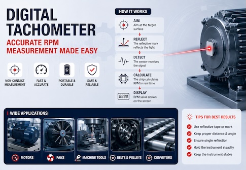
Light emission → Target reflection → Optical reception → Signal conversion → Pulse detection → RPM calculation → Digital display
Although circuit design and signal-processing algorithms vary between instruments, most laser and photoelectric non-contact tachometers follow this basic principle.
During measurement, the tachometer is aimed at a reflective mark on the rotating component. As the mark enters the detection area, the intensity of reflected light changes significantly. The photoelectric sensor detects this variation and converts it into an electrical signal that can be processed by the instrument.
The electronics then identify valid pulses, determine their frequency, and convert the result into RPM.
Step One: Emitting a Detection Beam Toward the Rotating Target
Once measurement begins, the tachometer directs a light beam toward the rotating component.
Some instruments use visible red light or a laser source. A visible beam also helps the operator confirm the detection point and align the instrument with the reflective mark on a shaft, disc, pulley, or other rotating surface.
When the light reaches the target, part of it is absorbed and part is reflected.
Because materials, colors, coatings, and surface textures reflect light differently, the rotating surface often needs a deliberately created high-reflectivity area that the tachometer can distinguish reliably.
Step Two: Using Reflective Tape to Create a Clear Optical Contrast
Many non-contact tachometer measurements use a small piece of reflective tape attached to the rotating target.
The reflective tape does not calculate speed itself. Its purpose is to create a strong contrast between the marked and unmarked areas so that the tachometer can reliably identify each revolution.
For example, when reflective tape is applied to a dark rotating shaft, the unmarked surface may return relatively little light, while the reflective tape produces a much stronger return signal.
As the shaft rotates, the reflected-light pattern becomes periodic:
● Unmarked surface passes the sensor: weaker reflected signal.
● Reflective tape passes the sensor: stronger reflected signal.
● Reflective tape moves away: signal decreases again.
● On the next revolution, the reflective tape returns and produces another cycle.
If only one reflective mark is used, each complete valid optical event can normally be treated as one revolution.
Step Three: Receiving Reflected Light with a Photoelectric Sensor
The reflected light returning to the tachometer is detected by an internal photoelectric sensor.
The sensor responds to changes in light intensity and converts them into electrical signals. As the reflective mark and normal surface alternately pass through the detection area, the electrical output also varies periodically.
Real-world optical signals, however, are rarely ideal.
Ambient lighting, shiny surfaces, mechanical vibration, changes in measuring distance, and reflections from nearby objects can introduce interference. The instrument therefore cannot treat every change in light level as a valid revolution.
For this reason, the internal electronics normally amplify, filter, and condition the sensor output so that genuine periodic signals generated by the rotating target can be distinguished more reliably from noise.
Step Four: Converting Reflected-Light Changes into Electrical Pulses
After signal conditioning, the varying optical signal is converted into electrical pulses that the instrument can count.
A simplified way to understand the process is that each time the reflective mark passes through the detection area, the tachometer records one valid pulse.
For example, if the shaft carries one reflective mark:
● First revolution: 1 valid pulse.
● Second revolution: another valid pulse.
● Third revolution: another valid pulse.
With one mark per revolution, the pulse count directly represents the number of revolutions.
The tachometer therefore does not calculate speed directly from the laser beam itself. It calculates speed from periodic electrical pulses obtained after optical detection and signal processing.
Step Five: Calculating RPM from Pulse Frequency
Once stable periodic pulses are available, the tachometer can calculate rotational speed.
RPM stands for Revolutions Per Minute, meaning the number of complete revolutions performed in one minute.
If the rotating target generates one valid pulse per revolution and the detected frequency is (f), the relationship can be expressed as:
RPM = 60 × f
Where:
● RPM = revolutions per minute.
● f = number of valid rotational pulses detected per second.
For example, if the instrument detects 20 valid pulses per second and there is one reflective mark per revolution:
RPM = 60 × 20 = 1200 RPM
The rotating component is therefore turning at approximately 1,200 revolutions per minute.
If several reflective marks are detected during each revolution, the instrument must account for the number of pulses generated per revolution. In such cases, one pulse can no longer automatically be treated as one complete revolution.
Why Is Only One Reflective Mark Normally Used?
For conventional handheld non-contact tachometers, one clear and stable reflective mark is generally the simplest way to obtain an accurate reading.
If a rotating target has two similar highly reflective areas and both are detected as valid marks, the tachometer may generate two pulses for every actual revolution.
If the instrument assumes that one pulse represents one revolution, the displayed speed may be approximately twice the actual rotational speed.
For reliable measurement:
● Use one clearly defined primary reflective mark per revolution.
● Avoid other highly reflective areas near the mark.
● Make sure screws, polished metal surfaces, or other reflections are not mistaken for additional targets.
The number and placement of reflective marks can therefore directly affect the measurement result.
What Role Does the Laser Play in a Non-Contact Tachometer?
A laser tachometer is one of the most common types of non-contact tachometer.
A laser or other directional light source provides a clearly defined detection area and helps the operator confirm where the instrument is aimed. At an appropriate distance, the visible spot makes it easier to align the tachometer with the path of the reflective mark.
However, the rotational speed is ultimately determined through optical reception and electronic signal processing.
A typical non-contact tachometer system therefore includes:
● Detection light source.
● Reflective target or reflective tape.
● Photoelectric receiver.
● Signal amplification and filtering circuits.
● Pulse-detection circuitry.
● Microprocessor or calculation circuit.
● LCD or other digital display.
These elements work together to convert mechanical rotation into a measurable RPM value.
Why Can a Non-Contact Tachometer Measure High Rotational Speeds?
One of the main advantages of non-contact measurement is that there is no mechanical contact between the tachometer and the rotating component.
With a contact tachometer, a measuring tip or wheel must physically touch the rotating shaft or surface. At high speeds, contact stability, operator safety, slipping, and mechanical loading all need to be considered.
A non-contact tachometer primarily relies on optical signals and therefore introduces no significant mechanical load through the measuring instrument.
Typical applications include:
● Motor shafts.
● Fans and blowers.
● Pulleys.
● Machine-tool spindles.
● Pumps and rotating machinery.
● Selected high-speed rotating equipment.
Non-contact measurement does not eliminate safety risks. High-speed rotating machinery can still present entanglement, ejection, or component-failure hazards, so the operator must maintain a safe distance from moving parts.
What Factors Affect Non-Contact Tachometer Measurements?
Because the instrument depends on a stable periodic optical signal, any factor that affects light emission, reflection, or reception can influence measurement stability.
● Insufficient reflective contrast: If the reflective tape does not differ enough from the surrounding surface, pulses may not be detected reliably.
● Multiple reflective areas: Screws, polished metal, or other bright surfaces may be interpreted as additional marks.
● Incorrect measuring distance: Beyond the specified operating range, the reflected signal may become too weak.
● Poor alignment: If the beam does not consistently cross the reflective mark, the signal may be intermittent.
● Strong ambient light: Intense sunlight or other strong light sources can reduce the optical signal-to-noise ratio.
● Excessive target vibration: Movement of the target away from the detection area can cause unstable readings.
● Unsuitable reflective-mark size: A mark that is too small may be difficult to detect, while an excessively large mark can affect signal transitions at high speed.
● Highly reflective rotating surfaces: Bright metal surfaces may produce unwanted reflections and reduce the contrast between the mark and background.
Reliable measurements therefore depend not only on the tachometer itself but also on target preparation and measurement conditions.
How to Obtain More Stable Non-Contact Tachometer Readings
Before measurement, inspect the rotating surface and choose a suitable location for the reflective mark.
● Clean the surface before applying reflective tape so that oil or dust does not affect adhesion.
● Normally use one clear reflective mark to avoid duplicate pulses.
● Aim the detection beam at the path followed by the reflective mark.
● Keep the instrument within its specified measuring distance.
● Hold the tachometer as steadily as possible during measurement.
● Wait until the reading stabilizes before recording the result.
● If the reading is unusually high, low, or unstable, check for multiple reflection points, loose reflective tape, or beam misalignment.
For repeated measurements or routine condition monitoring, using the same measuring location, distance, and angle improves comparability between readings.
How Does a Non-Contact Tachometer Differ from a Contact Tachometer?
The fundamental difference lies in how rotational motion is detected.
A non-contact tachometer uses photoelectric or laser detection to identify periodic signals from the rotating target without physically touching it.
A contact tachometer uses a contact tip, cone adapter, or measuring wheel to make direct mechanical contact with the shaft or moving surface. Mechanical motion is then transferred to the instrument for calculation of rotational or linear speed.
In general:
● Non-contact tachometers are suitable for high-speed, difficult-to-access, or unsuitable-to-touch rotating components.
● Contact tachometers are useful where direct mechanical contact is safe and practical.
● Neither method is universally better; the appropriate choice depends on the equipment and measurement conditions.
FAQ
Does a non-contact tachometer always require reflective tape?
Not necessarily. However, for most handheld reflective photoelectric tachometers, reflective tape significantly increases the contrast between the target and its background, improving detection reliability. If the rotating component already has one clear and unique reflective feature, direct measurement may sometimes be possible.
Why might the displayed speed be twice the actual RPM?
A common reason is that the tachometer detects two reflective points during each revolution. This can happen when two pieces of reflective tape are used or when another bright surface is detected. Two pulses per revolution can cause the displayed value to be approximately double the actual speed.
Why does the reading keep fluctuating?
Possible causes include poor reflective contrast, incorrect measuring distance, unstable aiming, target vibration, strong ambient light, or multiple reflective areas. The measurement setup should be checked systematically.
Can a non-contact tachometer display RPM directly?
Yes. The instrument automatically detects the periodic optical signal, calculates the corresponding frequency, and displays the resulting rotational speed directly in RPM or another supported unit.
Can a non-contact tachometer measure a stationary object?
Not in rotational-speed mode. RPM measurement requires a repeating signal generated by motion. A stationary target does not produce the periodic pulses needed for rotational-speed calculation.
Is a shorter measuring distance always better?
No. Each tachometer has a specified operating distance. Excessive distance can weaken the reflected signal, while being too close does not necessarily provide optimal detection. The recommended range in the product specifications should be followed.
Conclusion
A non-contact tachometer works by converting rotational motion into a periodic optical signal, then converting that signal into electrical pulses and calculating RPM.
In a typical measurement, the tachometer emits a detection beam toward a rotating target. A reflective mark periodically enters the detection area, the photoelectric sensor detects the change in reflected light, and the electronics convert that change into pulses. The instrument then determines pulse frequency and displays the corresponding rotational speed.
With a standard one-mark-per-revolution setup, the basic concept is simple: each time the reflective mark passes the sensor, the target has completed one revolution.
For reliable results, the reflective mark must be clear and unique, and the measuring distance, angle, ambient light, and target condition must all be appropriate. Understanding these principles makes it easier to obtain stable readings and diagnose abnormal measurement results.