Introduction
Rotational speed is an important parameter when evaluating motors, fans, rollers, drive shafts, and other rotating machinery. Where the rotating shaft or moving surface can be accessed safely, a contact tachometer provides a direct method of speed measurement.
Unlike non-contact tachometers that use laser or optical reflection, a contact tachometer requires a measuring tip or wheel to physically touch the object being measured. Mechanical motion is transferred into the instrument, detected by an internal sensor, converted into an electrical signal, and processed to display RPM, m/min, or another supported unit.
Understanding this operating process helps users select the correct attachment, maintain proper contact, and reduce measurement errors caused by slipping, misalignment, or excessive contact pressure.
Key Points
● A contact tachometer requires direct contact with a rotating shaft or moving surface.
● The contact tip or measuring wheel transfers mechanical motion to the internal measuring mechanism.
● An internal sensor converts rotational motion into electrical pulses or other processable signals.
● The processor calculates RPM from the number or frequency of detected pulses.
● With a suitable measuring wheel, many contact tachometers can also measure the linear speed of belts, conveyors, and rollers.
● Slippage, misalignment, unstable contact pressure, and surface condition can affect measurement accuracy.
What Is a Contact Tachometer?
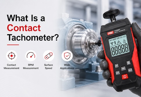
A contact tachometer is an instrument that measures rotational speed or surface speed through direct mechanical contact with the object being measured.
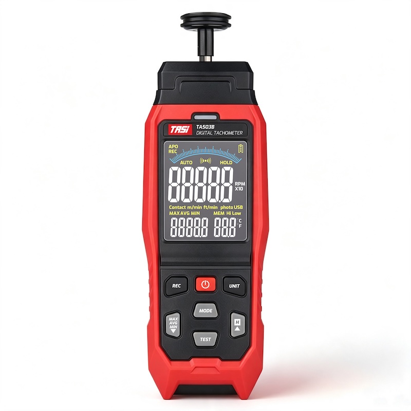
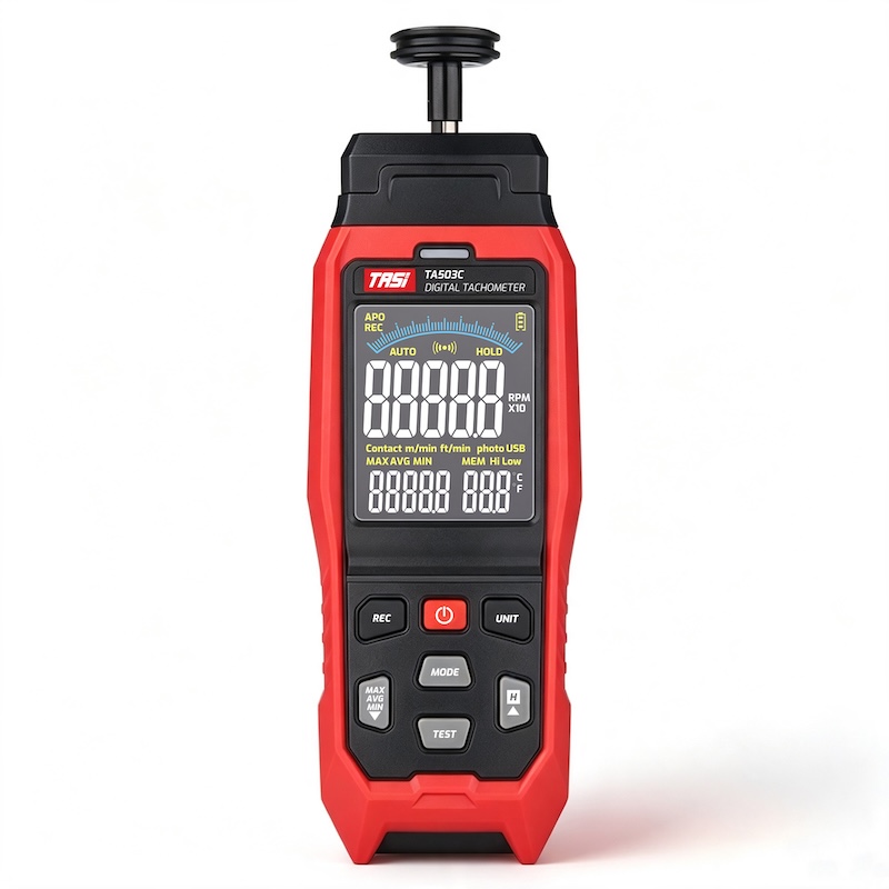
A typical digital contact tachometer consists of a contact tip, measuring shaft, internal rotational sensor, signal-conditioning circuit, microprocessor, and display.
For shaft-speed measurement, a conical or concave contact tip is normally fitted to the instrument. For surface-speed measurements on belts, conveyors, or rollers, a measuring wheel with a known circumference or diameter may be used.
Because the measurement is mechanical, no reflective tape is normally required, and the result is not directly affected by the colour or reflectivity of the rotating surface.
Basic Operating Principle of a Contact Tachometer
The operating process can be summarized as follows:
● Contact the moving object.
● Transfer its mechanical rotation to the instrument.
● Convert the mechanical motion into an electrical signal.
● Detect the number or frequency of rotations over a defined period.
● Calculate and display the rotational speed.
When a contact tip is pressed against the end of a rotating shaft, the shaft drives the contact tip. The tip then rotates the instrument's internal measuring shaft.
Depending on the instrument design, optical, magnetic, or other rotational sensing technologies may be used internally. As the measuring mechanism rotates, the sensor generates electrical pulses corresponding to the rotational movement.
The signal-conditioning circuit processes these pulses, and the microprocessor converts them into a speed reading, typically displayed in RPM.
How Is Mechanical Rotation Transferred into the Instrument?
Reliable mechanical contact is the first requirement for contact measurement.
When measuring a shaft, the operator places an appropriate contact tip against the centre of the rotating shaft end. The shaft drives the tip, which in turn drives the tachometer's internal measuring shaft.
Under ideal conditions:
● The measuring mechanism follows the shaft rotation proportionally.
● There is no significant slipping between the shaft and contact tip.
● The measuring axis is aligned as closely as possible with the shaft axis.
This mechanical synchronization is fundamental to accurate measurement.
If the contact tip slips, the internal measuring shaft may rotate more slowly than the actual shaft, resulting in a reading below the true speed. Poor alignment can also cause vibration and unstable readings.
How Is Rotational Speed Converted into an Electrical Signal?
Mechanical rotation must be converted into a signal that the electronic circuitry can process.
Digital contact tachometers generally include an internal sensing arrangement that generates periodic signals as the measuring shaft rotates. Depending on the design, one revolution may produce one pulse or multiple pulses.
The faster the measuring shaft rotates, the greater the pulse frequency.
For example, if one pulse represents one complete revolution and 20 pulses are detected in one second, the shaft is rotating at 20 revolutions per second:
20 × 60 = 1200 RPM
If the sensor produces multiple pulses per revolution, the processor automatically compensates for the configured pulses-per-revolution value.
How Does a Contact Tachometer Calculate RPM?
RPM stands for Revolutions Per Minute.
A digital tachometer does not normally need to count revolutions for a full minute. Instead, it measures pulse frequency during a much shorter sampling interval and converts the result into revolutions per minute.
The basic relationship is:
RPM = revolutions per second × 60
If the internal sensor produces several pulses per revolution, the calculation must also account for the number of pulses generated during each revolution.
For example, if the sensor produces four pulses per revolution and the instrument detects 80 pulses in one second:
80 ÷ 4 = 20 revolutions per second
20 × 60 = 1200 RPM
The instrument performs this calculation automatically and displays the final reading.
How Do Conical and Concave Contact Tips Work?
Contact tachometers are commonly supplied with different tip shapes to accommodate different shaft-end designs.
● Conical tips are suitable for shaft ends with a centre hole or another feature that allows the cone to remain centred.
● Concave tips are suitable for protruding shaft ends that can sit securely inside the recessed contact surface.
In both cases, the objective is to maintain stable mechanical engagement and keep the measuring axis aligned with the shaft.
The correct tip should be selected according to the geometry, size, and accessibility of the shaft rather than relying on excessive contact pressure to maintain engagement.
How Does a Measuring Wheel Determine Linear Speed?
In addition to RPM, many contact tachometers can measure linear surface speed using a measuring wheel.
The wheel has a known circumference or diameter. When pressed against a conveyor belt, drive belt, roller surface, or other moving object, the surface causes the wheel to rotate.
Provided there is no significant slipping, linear speed can be calculated from:
● The number of wheel revolutions per minute.
● The known wheel circumference.
For example, if the measuring wheel has a circumference of 0.1 m and rotates at 500 RPM:
500 × 0.1 = 50 m/min
Compatible digital tachometers perform this conversion automatically and may display m/min, ft/min, or other supported units.
Why Does Slippage Affect Contact Measurement?
Contact tachometers depend on mechanical motion transfer, so friction between the contact attachment and the measured object is important.
If contact pressure is too low, the tip may slip against the rotating shaft.
Oil, dust, wear, or contamination on a measuring wheel can also reduce friction and cause its rotational speed to fall below the actual surface speed.
However, excessive pressure is not desirable either. Too much force can increase mechanical load and may even reduce the actual rotational speed of small motors or low-torque mechanisms.
The correct approach is to maintain stable contact with sufficient pressure to prevent slipping without significantly loading the machine.
Why Should the Contact Tip Be Aligned with the Shaft Centre?
The position of the contact tip directly affects measurement stability.
If the contact point is significantly off-centre, the instrument may oscillate as the shaft rotates, producing vibration and changing the contact condition.
For reliable measurement:
● Align the tachometer shaft with the rotating shaft as closely as possible.
● Position the contact tip near the centre of the shaft end.
● Keep the instrument stable during measurement.
● Avoid pressing the contact tip against the shaft at a pronounced angle.
Good axial alignment improves reading stability and reduces unnecessary wear on the contact attachment.
What Factors Affect Contact Tachometer Accuracy?
Practical measurement accuracy depends on both instrument performance and mechanical conditions.
● Contact-tip slippage: may produce readings below the actual speed.
● Poor shaft alignment: may cause vibration and unstable readings.
● Insufficient pressure: may result in intermittent contact.
● Excessive pressure: may load the machine and alter its speed.
● Worn contact tips: may reduce grip and positioning stability.
● Worn measuring wheels: changes in effective diameter or circumference can affect linear-speed calculations.
● Oil or contamination: may cause slipping.
● Actual machine-speed fluctuation: changes in motor load, drive conditions, or control systems can also cause the displayed value to vary.
Reliable measurement therefore depends on both instrument specifications and correct measurement technique.
Typical Contact Tachometer Measurement Procedure
For rotational-speed measurement:
● Fit the correct conical or concave contact tip.
● Start the machine and confirm that operating conditions are stable.
● Switch on the tachometer and select RPM mode.
● Slowly move the contact tip toward the centre of the rotating shaft.
● Keep the tachometer axis aligned with the shaft.
● Apply light, steady pressure to maintain reliable contact.
● Wait for the reading to stabilize before recording or holding the value.
● Move the instrument smoothly away from the rotating part after measurement.
For surface-speed measurement, install the appropriate measuring wheel, select the required linear-speed unit, and maintain stable contact with the moving surface.
How Does a Contact Tachometer Differ from a Non-Contact Tachometer?
The main difference is how rotational information is acquired.
A contact tachometer mechanically transfers rotation from the measured object to the instrument.
A non-contact tachometer usually detects a reflective target using laser or optical sensing and does not need to touch the rotating part.
Contact measurement is suitable when the shaft end can be accessed safely and when direct shaft-speed or surface-speed measurement is required.
Non-contact measurement is generally more suitable for high-speed, hot, distant, or inaccessible rotating components.
Neither method is universally better. The appropriate choice depends on the machine structure, safety conditions, and measurement objective.
What Equipment Can Be Measured with a Contact Tachometer?
Typical applications include:
● Motor shafts.
● Fan and blower shafts.
● Pump shafts.
● Machine-tool spindles.
● Rollers.
● Conveyors.
● Drive belts.
● Printing and packaging machinery.
● Textile machinery.
● Laboratory rotating equipment.
Contact measurement should not be used where accessing the rotating component would create an unacceptable safety risk.
What Should Be Considered When Using a Contact Tachometer?
Because the instrument must be brought close to moving machinery, operating safety is essential.
● Confirm that the contact attachment is securely fitted before measurement.
● Keep hands, clothing, cables, and other objects away from rotating mechanisms.
● Do not apply excessive lateral force to the shaft.
● Confirm that the expected speed is within the rated measuring range of both the instrument and attachment.
● Where exposed blades, couplings, or other hazardous rotating parts are present, consider whether non-contact measurement is safer.
● Move the instrument away from the rotating part before changing attachments or measurement modes.
Contact measurement should only be performed where stable mechanical contact can be established safely.
FAQ
Does a contact tachometer always have to touch the rotating shaft?
For RPM measurement, the contact attachment normally touches the shaft end directly. For linear-speed measurement, the measuring wheel contacts the moving surface.
Why are different contact-tip shapes supplied?
Different shaft ends require different contact geometries. Conical and concave tips help improve positioning and mechanical stability.
Can a contact tachometer measure conveyor speed?
Yes. With a suitable measuring wheel, it can determine the linear speed of conveyors and similar moving surfaces.
Why can the reading be lower than the actual rotational speed?
Typical causes include slipping, insufficient contact pressure, worn attachments, poor shaft alignment, or contamination on the contact surface.
Does higher contact pressure improve accuracy?
Not necessarily. Insufficient pressure can cause slipping, while excessive pressure can introduce mechanical load and affect the actual speed.
Can a contact tachometer measure very high rotational speeds?
Only if the instrument, contact attachment, and operating conditions permit it. For very high-speed or inaccessible rotating parts, non-contact measurement is often more appropriate.
Conclusion
A contact tachometer works by converting mechanical rotational motion into an electrical signal that can be measured and processed.
The rotating shaft drives a conical or concave contact tip, which transfers motion to the tachometer's internal measuring mechanism. A sensor converts this movement into electrical pulses, and the processor uses the pulse frequency to calculate RPM. With a measuring wheel, the same principle can be used to determine linear surface speed.
Because the method relies on direct mechanical contact, alignment, contact pressure, surface condition, and slippage all influence measurement quality.
Correct attachment selection, proper operating technique, and careful attention to machinery safety are therefore essential for obtaining stable and reliable speed measurements.