Introduction
Rotational speed is an important parameter for evaluating the operating condition of motors, fans, drive shafts, pulleys, and other rotating machinery. Conventional contact measurement requires the measuring probe to physically touch the rotating component, whereas a photoelectric tachometer can measure speed without direct contact. This makes it particularly suitable for high-speed rotating parts, components that are difficult to reach, and applications where a safe working distance is required.
The basic operating principle is straightforward: the instrument detects a periodic optical signal produced once per revolution and calculates rotational speed from the number of detected signals over time.
Understanding this process helps users operate a photoelectric tachometer correctly and troubleshoot unstable readings, abnormal values, or measurement errors.
Key Points
● A photoelectric tachometer is a typical non-contact rotational speed measuring instrument.
● It identifies rotational cycles by transmitting light and detecting reflected optical signals from the rotating object.
● A reflective marker is normally applied to the rotating surface to create a clear optical contrast.
● Each valid reflected signal is converted into a corresponding electrical pulse.
● When one valid marker is used per revolution, the pulse rate can be converted directly into RPM.
● Reflective marker quantity, ambient light, measuring distance, surface reflectivity, and optical alignment can all affect measurement results.
What Is a Photoelectric Tachometer?
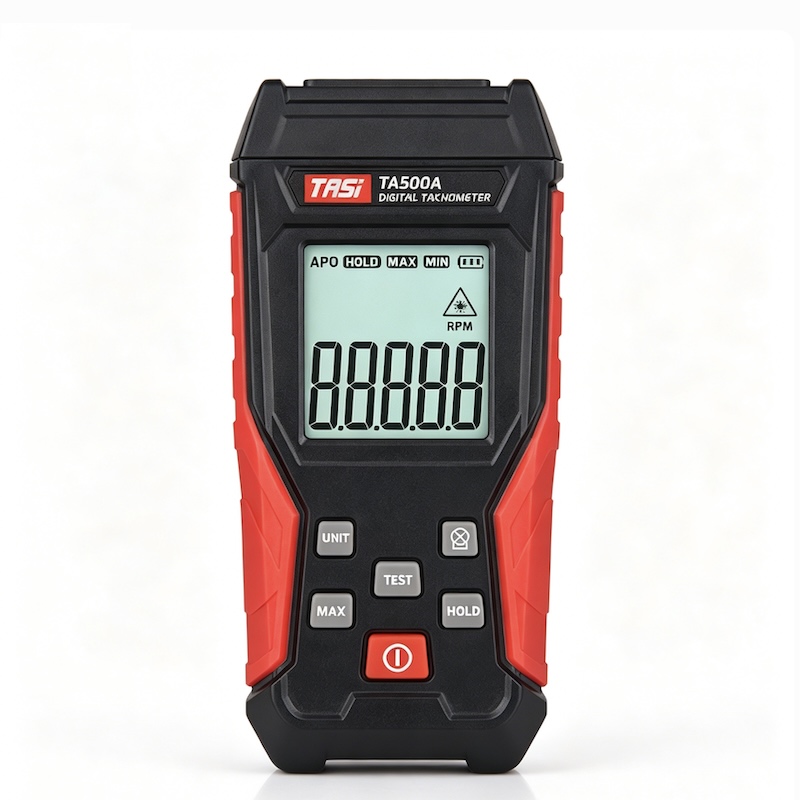
A photoelectric tachometer is an instrument that measures rotational speed using an optical transmitter, a photoelectric receiver, and electronic pulse-counting circuitry. It is generally classified as a non-contact tachometer.
During measurement, the instrument does not need to touch the motor shaft, fan impeller, or other rotating component. Instead, it directs a light beam toward a specific area on the rotating surface.
To create a clearly identifiable optical reference, a small piece of reflective tape is usually applied to the rotating component. Each time the reflective marker passes through the beam, the intensity of the reflected light changes significantly compared with the surrounding surface.
The photoelectric sensor detects this variation and converts it into an electrical pulse. By measuring the pulse frequency, the instrument can determine the rotational speed.
What Are the Main Components of a Photoelectric Tachometer?
Although designs vary between models, a typical photoelectric tachometer measurement system includes the following components:
● Light emitter: Produces the measuring beam directed toward the rotating object. Common sources include visible LEDs and lasers.
● Reflective marker: Usually reflective tape that creates a distinct periodic reflected signal.
● Photoelectric receiver: Detects the reflected light and changes in optical intensity.
● Signal-processing circuit: Amplifies, filters, shapes, and identifies the electrical signal generated by the sensor.
● Counting and calculation circuit: Counts valid pulses over a defined period and converts them into rotational speed.
● Display system: Shows the calculated rotational speed, normally in RPM.
Together, these components convert an optical signal into a digital rotational speed reading.
How Does a Photoelectric Tachometer Measure Rotational Speed?
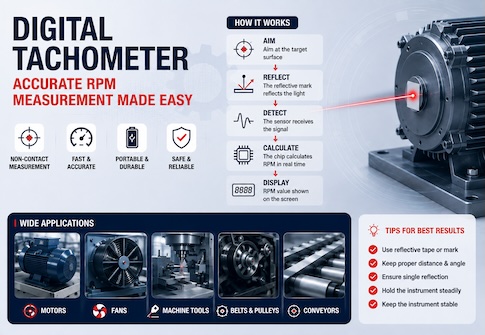
The measurement process can be summarized as “emit—reflect—detect—count—calculate.”
● Emit the measuring beam: The tachometer directs a stable beam toward the rotating surface.
● Detect changes in reflection: The normal surface produces one reflection level, while the reflective marker creates a clearly different reflected signal.
● Convert light into an electrical signal: The photoelectric sensor converts the detected optical variation into an electrical signal.
● Generate electrical pulses: The signal-processing circuit converts valid changes into pulses suitable for counting.
● Measure pulse frequency: The instrument determines how many valid pulses occur within a given time.
● Calculate rotational speed: The pulse frequency and the number of valid markers per revolution are used to calculate RPM.
A photoelectric tachometer therefore does not measure rotational speed directly. Instead, it measures the frequency of periodic optical events produced by rotation.
Why Can an Optical Signal Represent Rotational Speed?
Assume that only one piece of reflective tape is attached to a rotating shaft.
Each time the shaft completes one revolution, the reflective marker passes through the measuring beam once. The tachometer therefore detects one distinct reflected signal and generates one valid pulse per revolution.
If the shaft completes 1,000 revolutions in one minute, the instrument theoretically detects 1,000 corresponding periodic signals during that minute. The displayed speed is therefore approximately:
1,000 RPM
RPM stands for Revolutions Per Minute.
When there is one valid marker per revolution, rotational speed can also be expressed as:
RPM = 60 × f
Where:
● RPM is rotational speed in revolutions per minute.
● f is the detected pulse frequency in hertz.
For example, if the instrument detects 25 valid pulses per second:
RPM = 60 × 25 = 1,500 RPM
This relationship forms the basis of photoelectric rotational speed measurement.
Why Is Only One Reflective Marker Normally Used?
Photoelectric tachometers determine speed by counting periodic signals, so the number of reflective markers directly affects the number of detected pulses.
If one marker passes through the detection area once per revolution, one detected signal corresponds to one complete revolution.
If two equally detectable reflective markers are placed around the same rotating circumference, two valid pulses may be generated during every revolution.
For a standard tachometer configured on the assumption of one pulse per revolution, an actual speed of 1,000 RPM could therefore be displayed as approximately 2,000 RPM.
For normal rotational speed measurement:
● Use only one valid reflective marker per revolution.
● Avoid nearby bright surfaces that may produce additional strong reflections.
● Ensure sufficient optical contrast between the reflective tape and the surrounding surface.
Correct placement of the reflective marker is therefore essential for reliable measurement.
What Is the Purpose of Reflective Tape?
Many rotating surfaces have relatively uniform colour and reflectivity. Without a distinct optical feature, the sensor may be unable to determine when one full revolution has been completed.
Reflective tape creates an artificial optical reference that is easy for the sensor to identify.
When the light beam strikes the normal surface, the receiver detects one reflection level. When the reflective marker passes through the beam, the reflected intensity changes significantly. The tachometer uses this periodic variation to identify each rotational cycle.
The reflective tape does not itself calculate speed. Its function is to provide a stable and clearly distinguishable reference signal for the optical detection system.
If the rotating object already has a reliable high-contrast feature, reflective structure, or other distinct optical reference, additional reflective tape may not be necessary, provided the instrument can detect the feature consistently.
Does a Laser Tachometer Use the Same Principle?
Yes.
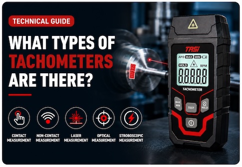
A laser tachometer is generally a type of photoelectric tachometer. It uses a laser as the measuring light source, providing a narrow, clearly visible beam that helps the operator identify the measurement point.
The basic signal-processing sequence remains the same:
● Emit a light beam.
● Direct the beam at the rotating object.
● Detect the stronger periodic reflection from the reflective marker.
● Convert the optical change into an electrical signal.
● Generate and count pulses.
● Calculate RPM from the pulse frequency.
The term “laser tachometer” mainly describes the type of light source and practical measurement method. Its core principle remains photoelectric non-contact speed measurement.
What Factors Affect Photoelectric Tachometer Accuracy?
Although photoelectric measurement avoids direct mechanical contact, measurement performance can still be affected by optical conditions and operating technique.
● Poor reflective marker condition: A marker that is too small, dirty, damaged, or insufficiently reflective may produce a weak signal.
● Multiple reflective points: Bright metal surfaces, screws, edges, or other reflective features may create additional pulses and cause false counting.
● Incorrect measuring distance: The reflected signal may become too weak outside the specified operating distance.
● Unstable measuring angle: If the beam does not consistently intersect the marker path, signals may be missed.
● Ambient light interference: Strong sunlight, intense lighting, or periodically flickering light sources may interfere with optical detection.
● Mechanical vibration: Excessive shaft or component movement may cause the reflective marker to move outside the measuring beam.
● Incorrect number of reflective markers: Multiple effective markers can create a pulse frequency higher than the actual rotational frequency.
If the reading is abnormally high, low, or unstable, the optical signal and measurement setup should be checked before assuming that the instrument is defective.
How Should a Photoelectric Tachometer Be Used Correctly?
For stable and reliable measurements:
● Apply one suitable reflective marker to a location where the measuring beam can reach it consistently.
● Ensure there are no other highly reflective areas close to the marker.
● Start the machine and aim the tachometer steadily at the path followed by the reflective marker.
● Keep the instrument within its specified measuring distance.
● Hold the tachometer as steadily as possible so the beam remains on the target path.
● Wait for the displayed value to stabilise before recording the result.
● If the reading is abnormal, adjust the distance, angle, or marker position and repeat the measurement.
For high-speed rotating equipment, non-contact measurement helps avoid physical contact with moving components. However, operators must still maintain a safe distance and must never attempt to apply reflective tape or reposition the target while the machine is running.
What Are the Main Advantages of a Photoelectric Tachometer?
Compared with mechanical or contact tachometers, photoelectric tachometers offer several advantages:
● No mechanical pressure is applied to the rotating shaft.
● The measurement does not introduce additional mechanical load.
● Suitable for relatively high rotational speeds.
● Useful for components that are difficult to access physically.
● Allows a safe distance to be maintained from rotating machinery.
● Provides fast measurements for maintenance and routine inspection.
However, because the method depends on stable optical detection, greater attention is required when surface reflections are complex, the target vibrates significantly, or the optical path is obstructed.
Where Are Photoelectric Tachometers Used?
Photoelectric tachometers are widely used for quick rotational speed checks in industrial and maintenance applications, including:
● Motor shaft speed measurement.
● Fan and blower speed inspection.
● Pump, motor, and drive-system maintenance.
● Machine-tool spindle speed measurement.
● Pulley and drive-shaft speed measurement.
● Centrifugal equipment inspection.
● Installation, commissioning, and maintenance of rotating machinery.
They are particularly useful when the rotating speed is high or direct physical contact with the rotating part is impractical.
FAQ
What is the difference between a photoelectric tachometer and a laser tachometer?
A laser tachometer is generally a type of photoelectric tachometer that uses a laser as its measuring light source. Both detect periodic reflected optical signals and convert them into electrical pulses to calculate rotational speed.
Does a photoelectric tachometer always require reflective tape?
Not necessarily. If the rotating object already has a distinct optical feature that the sensor can detect consistently, measurement may be possible without additional reflective tape. In most field applications, however, reflective tape provides a clearer and more stable signal.
Why can using two reflective markers double the reading?
If the tachometer assumes one pulse per revolution, two detectable markers generate two pulses per revolution. As a result, the displayed speed may be approximately twice the actual rotational speed.
Why is there no reading even though the beam is aimed at the rotating object?
Possible causes include insufficient optical contrast, incorrect reflective tape position, excessive measuring distance, unstable beam alignment, strong ambient light interference, or excessive vibration of the rotating part.
Can a photoelectric tachometer measure very high rotational speeds?
Photoelectric measurement is well suited to high-speed rotation, but the maximum measurable speed depends on the sensor response, signal-processing capability, and specified measurement range of the individual instrument.
Conclusion
A photoelectric tachometer measures rotational speed by converting periodic optical changes into electrical pulses and calculating RPM from the pulse frequency.
In a typical measurement setup, the reflective marker passes through the measuring beam once for every complete revolution, generating one valid periodic signal. When one marker is used per revolution, the pulse frequency can be directly related to the actual rotational speed.
Measurement accuracy therefore depends not only on instrument performance, but also on reflective marker placement, measuring distance, optical alignment, ambient light conditions, and the mechanical stability of the rotating object.
Understanding the sequence rotation → optical signal → electrical signal → pulse counting → RPM is the key to understanding how a photoelectric tachometer works and how to use it correctly.