Introduction
Rotational speed is an important operating parameter for motors, fans, drive shafts, pulleys, machine-tool spindles, and many other rotating machines. It not only indicates how fast equipment is running but can also provide useful information for performance verification, maintenance, wear assessment, and fault diagnosis.
The basic purpose of a tachometer is to determine how many revolutions a rotating object completes within a defined period and express the result in RPM (revolutions per minute).
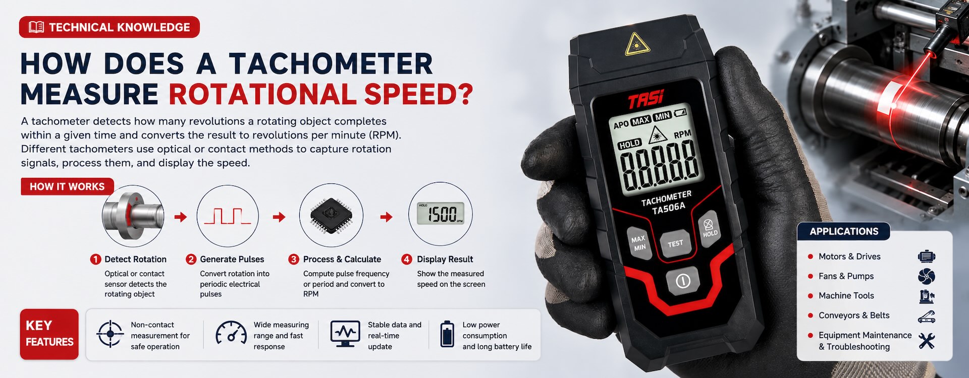
Although tachometers may use different sensing methods, the basic measurement process is similar:
● Detect rotational motion;
● Convert the rotational motion into a periodic signal;
● Measure the signal frequency or period;
● Convert the measured value into rotational speed;
● Process and display the result.
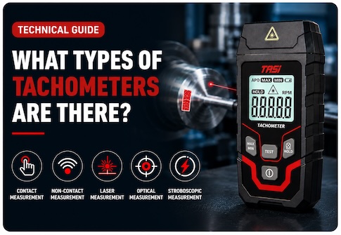
For portable tachometers, the two most common measurement methods are non-contact optical measurement and contact measurement.
Key Points
● Rotational speed is commonly expressed in RPM, meaning the number of revolutions completed per minute.
● A tachometer does not directly “see” RPM. It first detects periodic signals generated by the rotating object and then calculates the speed.
● Non-contact tachometers typically use an optical sensor to detect a reflective target passing through the measurement point.
● Contact tachometers obtain rotational speed through direct mechanical contact with a shaft or moving surface.
● RPM can be calculated either by counting pulses within a defined time interval or by measuring the time between successive pulses.
● Reflective target quantity, measurement position, surface condition, contact stability, and changes in actual machine speed can all affect the measurement result.
What Is Rotational Speed?
Rotational speed describes how many complete revolutions an object makes within a given period. In industrial measurement, the most common units are r/min and RPM, which normally represent the same quantity.
For example:
● 600 RPM means the object completes 600 revolutions per minute;
● 1,500 RPM means 1,500 revolutions per minute;
● 3,000 RPM means 3,000 revolutions per minute.
If a shaft rotates 25 times per second:
25 × 60 = 1,500 RPM
The essential principle of rotational speed measurement is therefore to determine the relationship between the number of revolutions and elapsed time.
Instead of tracking the complete mechanical movement continuously, a tachometer typically detects a repeatable feature that represents one revolution. Once this periodic feature can be identified reliably, rotational speed can be calculated.
Basic Principle of Tachometer Measurement
Whether the instrument uses optical sensing, mechanical contact, or another detection method, the core principle is similar: mechanical rotation is converted into a periodic signal that can be processed electronically.
Assume one pulse is generated for every complete revolution.
If the tachometer detects 20 pulses in one second and each pulse represents one revolution:
20 × 60 = 1,200 RPM
The shaft is therefore rotating at 1,200 RPM.
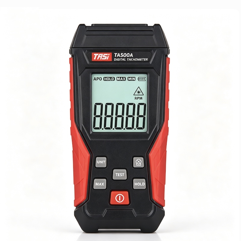
A typical digital tachometer combines a sensor, signal-conditioning circuitry, timing electronics or a microprocessor, and a display.
● The sensor detects rotational motion;
● The signal-conditioning circuit converts the raw sensor output into a stable electrical pulse;
● The processor counts pulses or measures the interval between them;
● The calculation algorithm converts the signal into RPM;
● The display presents the final measured value.
From a signal-processing perspective, the tachometer is therefore measuring a frequency or period associated with rotation, while RPM is the calculated output.
How Does a Non-Contact Tachometer Measure Speed?
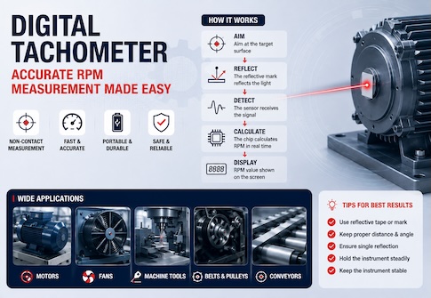
A non-contact tachometer generally uses an optical detection principle and does not need to touch the rotating component. This makes it suitable for motors, fans, pulleys, machine-tool spindles, shafts, and other high-speed rotating parts.
For many optical tachometers, a small piece of reflective tape is attached to the rotating object.
The instrument directs light toward the target area. When the beam strikes an ordinary surface, the useful reflected signal may be relatively weak. When the reflective tape passes through the sensing area, the sensor receives a much stronger change in reflected light.
The optical sensor converts this change into an electrical pulse.
If only one reflective target is used:
● Each pass of the reflective target represents one revolution;
● Each valid pulse can therefore correspond to one complete revolution;
● The number of pulses detected over time can be converted into RPM.
For example, if 25 pulses are detected in 0.5 seconds:
25 ÷ 0.5 × 60 = 3,000 RPM
Some non-contact tachometers use a visible light beam or laser for aiming. Its main purpose is to help the operator locate the correct measurement area, while the actual rotational speed measurement relies on the internal optical sensing system detecting periodic reflected signals.
Why Is Reflective Tape Commonly Used?
Rotating surfaces can vary greatly in color, texture, gloss, and reflectivity. Measuring directly from metal, plastic, painted, or uneven surfaces may produce inconsistent optical signals.
Reflective tape creates a clearly identifiable optical reference so that the sensor can distinguish each revolution more reliably.
Ideally, every revolution should generate one clear, repeatable signal.
When using reflective tape:
● Attach it securely so that it cannot detach at high speed;
● Keep the target area clean;
● Aim the instrument so that the sensing beam consistently crosses the target;
● Avoid other highly reflective surfaces near the measurement point;
● If the instrument assumes one pulse per revolution, normally use one effective reflective target.
If two identical reflective targets are placed on the rotating object and the instrument is configured for one pulse per revolution, two pulses may be detected during every revolution. The displayed speed could therefore be approximately twice the actual rotational speed.
How Does a Contact Tachometer Measure Speed?
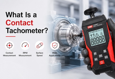
A contact tachometer uses a contact tip, cone, or other mechanical accessory that directly touches the rotating shaft.
During measurement, the shaft drives the tachometer's contact mechanism. An internal sensor then detects the rotation of this mechanism and converts it into an electrical signal.
A typical measurement sequence is:
● The contact attachment is placed securely against the rotating shaft;
● The shaft drives the contact mechanism;
● An internal sensor converts the motion into electrical pulses;
● The processor calculates rotational speed from the pulse signal;
● The measured RPM is shown on the display.
This method does not require reflective tape and can be convenient where reliable optical detection is difficult.
However, contact pressure, alignment, and slippage between the attachment and the rotating shaft can affect the result.
How Does a Contact Tachometer Measure Surface Speed?
Some contact tachometers can also use a measuring wheel to determine the linear speed of conveyor belts, cables, paper, wire, and other moving surfaces.
In this mode, the instrument first measures the rotational speed of the wheel and then converts it into linear speed using the wheel circumference.
For every complete wheel revolution, the moving surface theoretically travels a distance equal to the circumference of the measuring wheel.
Therefore:
Linear speed = Measuring wheel circumference × Number of wheel revolutions per unit time
Because the instrument is configured for the dimensions of the appropriate measuring wheel, it can usually display linear speed directly in units such as m/min, m/s, or ft/min.
The wheel must remain in stable contact with the moving surface. If slipping occurs, the wheel speed will no longer accurately represent the actual surface speed.
How Is RPM Calculated from Pulses?
Digital tachometers commonly use two calculation methods: frequency counting and period measurement.
With frequency counting, the instrument counts the number of valid pulses detected within a fixed time interval.
If one pulse corresponds to one revolution:
RPM = Revolutions per second × 60
For example, if 50 pulses are detected per second:
50 × 60 = 3,000 RPM
Another method measures the time interval between two successive pulses.
If one complete revolution takes 0.02 seconds:
Revolutions per second = 1 ÷ 0.02 = 50
Therefore:
50 × 60 = 3,000 RPM
Modern digital tachometers normally use a microprocessor for timing, filtering, calculation, and display. Depending on the instrument design and current speed, the processing method may be optimized to balance response time with reading stability.
Why Does the Tachometer Reading Sometimes Fluctuate?
Actual machines do not necessarily rotate at a perfectly constant speed. A small variation in the displayed value does not automatically indicate a problem with the instrument.
Possible causes include:
● Normal motor speed variation;
● Changes in mechanical load;
● Mechanical vibration;
● Unstable optical reflection;
● Changes in measurement distance or angle;
● Slight slippage during contact measurement;
● Continuous updating of the real-time speed value.
Digital tachometers may apply filtering, averaging, or other signal-processing techniques to improve display stability.
There is usually a balance between display stability and response speed. More averaging may produce a steadier reading, but rapid speed changes may take slightly longer to appear on the display.
Factors Affecting Non-Contact Measurement Accuracy
Non-contact measurement avoids direct contact with high-speed rotating components, but reliable optical signal quality remains important.
Common factors include:
● Reflective target quality: A target that is too small, dirty, damaged, or poorly attached can cause unstable detection.
● Measurement distance: The instrument should be used within its specified operating distance. Excessive distance may reduce reflected signal strength.
● Measurement angle: The sensing beam should consistently cover the path of the reflective target.
● Target surface: Highly reflective metal or other reflective areas can sometimes generate unwanted optical signals.
● Ambient light: Very strong light entering the sensor may affect some optical detection systems.
● Number of reflective targets: The target count must correspond to the pulse-per-revolution setting or calculation method.
The key to reliable optical tachometer measurement is not simply aiming light at a rotating object, but obtaining a clear, stable periodic signal that correctly represents each revolution.
Factors Affecting Contact Measurement Accuracy
Errors during contact measurement are mainly associated with the mechanical contact condition.
● The contact attachment is not aligned correctly with the shaft;
● The instrument moves excessively during measurement;
● Insufficient contact pressure causes slipping;
● Excessive pressure applies an additional load to the rotating mechanism;
● The contact tip is worn or contaminated with oil;
● The measuring wheel does not maintain stable contact with the moving surface.
For contact measurements, keep the instrument stable and use an attachment suitable for the shaft or surface being measured.
For high-speed, small, inaccessible, or potentially hazardous rotating parts, non-contact measurement is usually the more appropriate choice.
What Is the Difference Between Non-Contact and Contact Measurement?
Both methods are designed to determine rotational speed, but they use different sensing principles.
● Non-contact measurement: Uses optical signals without touching the rotating component and is particularly suitable for high-speed or difficult-to-access machinery.
● Contact measurement: Uses a mechanical attachment in direct contact with the rotating shaft and is suitable when the shaft can be accessed safely.
● Surface speed measurement: Normally uses a contact measuring wheel to convert wheel rotation into linear speed.
Some digital tachometers support both contact and non-contact measurement, allowing the operator to select the appropriate method according to machine design, speed range, access conditions, and safety requirements.
Measurement method selection should therefore consider not only convenience but also rotational speed, accessibility, measuring distance, and operator safety.
Applications of Rotational Speed Measurement in Maintenance
Rotational speed measurement does more than indicate how fast a machine is running. It can also help technicians verify whether equipment is operating as expected.
Typical applications include:
● Checking whether a motor is operating close to its rated or programmed speed;
● Verifying fan operating conditions;
● Comparing rotational speed before and after maintenance;
● Checking belt-drive systems for significant speed loss or slippage;
● Setting up machine-tool spindles and other rotating equipment;
● Verifying actual mechanical speed after variable-frequency drive adjustment;
● Comparing machine operation under different load conditions.
Rotational speed is only one machine-condition parameter. For equipment diagnostics, it is often evaluated together with vibration, temperature, current, noise, and other operating data.
FAQ
Does a tachometer measure speed or frequency?
From a signal-processing perspective, a digital tachometer usually measures the pulse frequency or period associated with rotation and then converts it into RPM. The final displayed quantity is rotational speed.
Does a laser tachometer measure rotational speed directly with the laser?
Most handheld non-contact tachometers use an optical sensor to detect changes in reflected light. A visible laser may assist with aiming, while the actual speed calculation is based on periodic optical signals generated by the rotating target.
Why is reflective tape normally required for non-contact measurement?
Reflective tape creates a distinct and stable optical reference on the target surface, allowing the sensor to identify each revolution more reliably.
Can multiple reflective targets be placed on one shaft?
Only if the instrument's pulse configuration is set accordingly. If the tachometer assumes one pulse per revolution but two effective targets are present, the displayed RPM may be approximately twice the actual value.
Which is more accurate, a contact or non-contact tachometer?
Accuracy cannot be determined solely by the measurement method. Both can provide reliable measurements when the instrument meets the required specifications and the correct procedure is used. Accuracy also depends on range, resolution, sensor performance, and measurement conditions.
Can a tachometer measure belt speed?
If the tachometer supports contact linear-speed measurement and uses a suitable measuring wheel, it can measure the surface speed of belts, conveyors, cables, and similar moving materials.
Conclusion
The fundamental principle of tachometer measurement is to convert mechanical rotation into a periodic signal and then calculate RPM from either the number of pulses detected within a defined time or the interval between successive pulses.
A non-contact tachometer typically uses an optical sensor to detect a reflective target, generating a pulse associated with each revolution. A contact tachometer obtains mechanical rotation through a contact tip or measuring wheel and converts that motion into an electrical signal.
The overall measurement process can therefore be summarized as:
Rotational motion → sensing → pulse signal → frequency/time calculation → RPM display
Understanding this process helps users select the appropriate contact or non-contact measurement method and avoid errors caused by poor reflective targets, incorrect measurement distance, slippage, or improper operating technique.