Introduction
A non-contact voltage tester, commonly referred to as an NCV tester, is a handheld tool used to quickly determine whether an AC electric field is present near wires, outlets, electrical equipment, and other energized locations.
Unlike traditional test methods that require direct electrical contact with a conductor, an NCV tester normally detects the alternating electric field surrounding an energized conductor. Its internal electronics process the induced signal and then provide a visual, audible, or display indication.
Although the tester appears simple from the outside, reliable non-contact voltage detection requires several functional components working together. Designs vary by model, but the basic architecture is generally similar.
Key Takeaways
● A typical NCV tester consists of a sensing tip, voltage-sensing circuit, signal-processing electronics, control circuit, indicators, power supply, and insulated housing.
● The sensing tip detects the electric field around an energized AC conductor rather than directly measuring the conductor voltage.
● Amplification and filtering circuits process the very weak induced signal before a detection decision is made.
● LEDs and buzzers are the most common warning methods, while some models also provide a display or voltage-range indication.
● Sensitivity selection, flashlight functions, and automatic power-off are optional features available on certain models.
● An NCV tester is useful for preliminary voltage screening but should not automatically be treated as a substitute for an appropriate voltage-measuring instrument or an approved absence-of-voltage verification procedure.
Basic Structure of a Non-Contact Voltage Tester
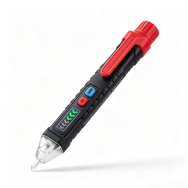
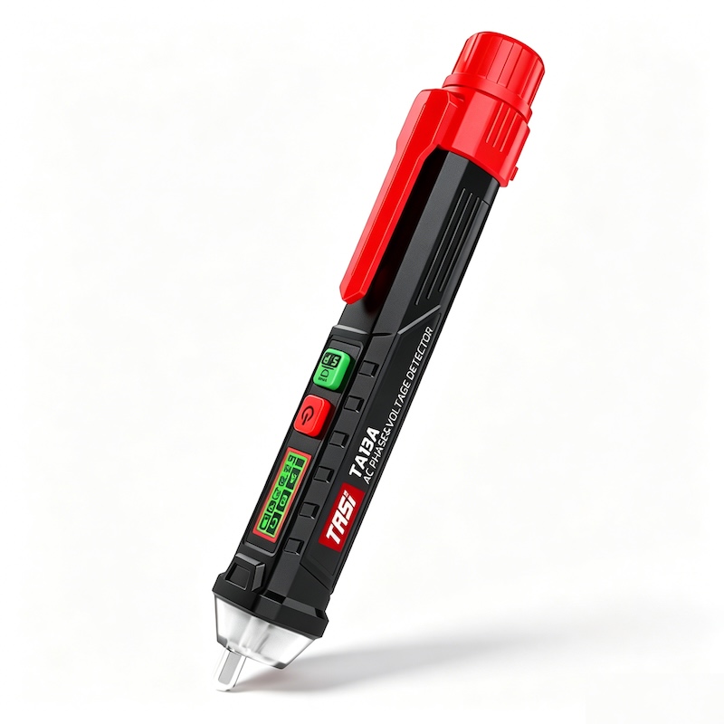
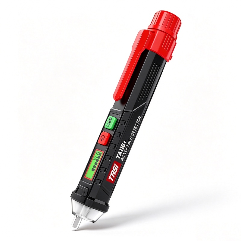
Although the mechanical design and feature set vary between manufacturers and models, a typical non-contact voltage tester can be divided into the following functional parts:
● Sensing tip or sensing area;
● Non-contact voltage-sensing circuit;
● Signal amplification and filtering circuit;
● Control and decision circuit;
● LED indicators, buzzer, or display;
● Function buttons;
● LED flashlight or other auxiliary functions;
● Battery and power-management section;
● Insulated housing, battery compartment, and pocket clip.
Together, these components perform the complete process from sensing an AC electric field to providing a user-visible or audible warning.
Sensing Tip
The sensing tip is normally located at the front of the tester and is the part positioned closest to a wire, outlet, or other test point.
Its main purpose is to detect the alternating electric field surrounding an energized AC conductor. When the tip approaches the conductor, the changing electric field can create a very small induced signal inside the tester through capacitive coupling.
This is fundamentally different from a conventional multimeter probe.
A multimeter normally establishes direct electrical contact with the test point, whereas an NCV tester primarily senses changes in the electric field and generally does not require its sensing tip to contact exposed live metal.
In many designs, the sensing electrode is located inside an insulated plastic tip to reduce the likelihood of direct contact with an energized conductor.
Non-Contact Voltage-Sensing Circuit
The signal captured by the sensing tip is extremely small and therefore requires a dedicated high-input-impedance detection stage.
This section can be considered the front-end electronics of the NCV function.
When the tester is brought near an energized AC conductor, capacitive coupling exists between the conductor, tester, user, ground, and surrounding environment. The sensing circuit receives the resulting signal and passes it to the next processing stage.
Because the tester detects an electric field rather than making a direct electrical connection, the result can be influenced by factors such as insulation thickness, test distance, shielding, grounding conditions, the user's position, and nearby energized conductors.
For this reason, an NCV tester is best suited to rapid screening and locating tasks rather than precision voltage measurement.
Signal Amplification and Filtering Circuit
The signal from the sensing tip is normally too weak to drive an indicator or buzzer directly, so additional signal conditioning is required.
The signal-processing stage typically performs functions such as:
● Amplifying the weak induced signal;
● Filtering unwanted interference;
● Determining whether the signal exceeds a predefined detection threshold;
● Passing the processed result to the control circuit.
In real electrical environments, multiple cables, electrical equipment, and electromagnetic interference sources may be present at the same time. Without suitable signal processing, the tester may become more susceptible to false indications or unstable detection.
Sensing sensitivity and signal-processing performance therefore have a major influence on practical NCV tester behavior.
Control and Decision Circuit
After signal conditioning, the processed signal is sent to the control and decision stage.
Basic testers may use comparator-based circuits, while more advanced digital models may use a microcontroller.
Depending on the design, the control electronics may operate:
● LED indicators;
● The buzzer;
● LCD or other display devices;
● High/low sensitivity modes;
● The flashlight;
● Automatic power-off;
● Low-battery indication.
Some NCV testers also vary the buzzer rate or LED flashing frequency according to signal strength, helping the user estimate the relative proximity of the sensing tip to an energized location.
However, the detected signal strength should not normally be interpreted as an accurate measurement of the actual circuit voltage.
LED Indicators
LEDs are among the most common indication devices used in non-contact voltage testers.
When the tester detects an AC electric field that meets its internal detection criteria, the control circuit activates or flashes the LED to warn the user that an energized conductor may be nearby.
Depending on the model, indication methods may include:
● A single LED turning on;
● A flashing LED;
● Different colors for different operating states;
● A flashing rate that changes with detected signal strength;
● Multiple LED segments representing different detection levels.
Some testers also use a separate power indicator so that users can distinguish between “tester switched on” and “voltage detected.”
Buzzer
Many NCV testers include an audible buzzer in addition to visual indicators.
When an AC electric field is detected, the tester can produce an audible warning so that the user does not need to continuously watch the LED.
In some designs, the beep rate increases as the detected signal becomes stronger or as the tip moves closer to an energized area.
Combined audible and visual indication is particularly useful when working inside distribution panels, behind equipment, or in poorly lit locations.
In noisy industrial environments, however, the buzzer may be difficult to hear, so users should not rely on sound alone.
Display Area
Not every NCV tester includes a display.
Basic models typically rely only on LEDs and a buzzer, while more feature-rich digital testers may include an LCD or other display to show:
● Operating status;
● High or low sensitivity mode;
● Battery status;
● Voltage level or detection range;
● Other auxiliary measurement information.
It is important to distinguish between an indicated voltage range and a directly measured voltage value.
Some NCV testers display only an approximate voltage category derived from field strength rather than an actual voltage measurement comparable to that obtained with a digital multimeter.
Users should therefore understand what the displayed information represents on the specific model being used.
Function Buttons
Modern non-contact voltage testers often include one or more control buttons.
Depending on the product design, these buttons may be used to:
● Switch the tester on or off;
● Select detection sensitivity;
● Turn the flashlight on or off;
● Enable or disable audible indication;
● Select other auxiliary functions.
Buttons are normally positioned on the front or side of the tester so that they can be operated with one hand.
Some models use short-press and long-press combinations to provide multiple functions from a single button.
Sensitivity Adjustment
Some NCV testers provide two or more sensitivity levels.
A high-sensitivity mode may be useful for detecting weaker electric fields, lower-voltage ranges, or energized conductors from a greater distance, but it may also respond more easily to adjacent wiring and environmental electric fields.
A low-sensitivity mode generally requires the sensing tip to be positioned closer to the energized conductor. This can help narrow the detection area when multiple wires are located close together.
Higher sensitivity therefore does not automatically mean better performance in every situation. The appropriate mode depends on the application and surrounding electrical environment.
LED Flashlight
Many pen-style NCV testers incorporate an LED flashlight near the front of the instrument.
The flashlight normally does not participate in voltage detection. Its purpose is to illuminate areas such as:
● Distribution panels;
● The rear of equipment;
● Outlets;
● Cable trays;
● Poorly lit maintenance areas.
For field electricians and maintenance personnel, this can be a practical auxiliary feature.
Depending on the model, the flashlight may be controlled independently or integrated into the tester's operating sequence.
Battery and Power Management
The electronic circuitry inside an NCV tester requires a power source, usually one or more small replaceable batteries.
The power section supplies operating voltage to the sensing, processing, control, indication, and lighting circuits.
To reduce unnecessary battery drain, some products provide:
● Automatic power-off;
● Low-battery indication;
● Standby management;
● Independent flashlight control.
Low battery voltage can affect detection or indication performance. Users should therefore confirm that the tester powers on correctly and that its indicators are functioning before use.
Insulated Housing
The insulated housing is both a mechanical component and an important part of the tester's safety design.
It encloses the electronic circuitry and battery while providing mechanical protection and separation between the internal components and the user's hand.
Common structural features include:
● Insulated plastic housing;
● Anti-slip grip area;
● Protected sensing tip;
● Battery compartment;
● Button area;
● Pocket clip.
Whether a tester is suitable for a particular electrical environment should not be judged only by the appearance of its insulated housing. Users should also check the manufacturer's rated operating range, applicable safety category, and operating instructions.
Pocket Clip and Mechanical Structure
Many NCV testers use a slim pen-style housing with an integrated pocket clip.
The clip allows the instrument to be attached to a workwear pocket, tool pouch, or tool belt and normally plays no role in electrical detection.
The pen-shaped form improves portability while allowing the narrow sensing end to reach outlets, cables, and confined test locations.
For technicians who perform frequent inspections and maintenance, this design can make the tool easier to carry and use.
How Do the Components Work Together?
When a non-contact voltage tester approaches an energized AC conductor, its operation can be simplified as follows:
● The energized conductor produces an alternating electric field;
● The sensing tip detects a weak signal through electric-field coupling;
● The sensing circuit receives the induced signal;
● Amplification and filtering circuits condition the signal;
● The control circuit determines whether the signal meets the detection threshold;
● If the detection criteria are met, the LED, buzzer, or display provides an indication.
An NCV tester is therefore not simply a sensing tip connected to a warning light. It is an electronic detection system combining field sensing, signal conditioning, decision logic, and user indication.
Why Do Different NCV Testers Perform Differently?
Even when two products are both described as non-contact voltage testers, their practical behavior can differ.
Possible reasons include:
● Different sensing-tip designs;
● Different input sensitivity;
● Different detection thresholds;
● Different filtering methods;
● Availability of multiple sensitivity levels;
● Different control algorithms;
● Different housing and sensing-area designs.
The test object and surrounding environment also affect the result.
Deeply recessed wiring, thick insulation, metallic shielding, closely grouped cables, and changes in the capacitive coupling between the user and ground may all affect detection distance and indication behavior.
For this reason, a tester that activates from a greater distance is not automatically more accurate.
How Does an NCV Tester Differ from a Traditional Contact Voltage Tester?
The main difference lies in the detection method.
Traditional contact-type testers generally require direct electrical contact between a probe and the test point before the internal circuit can evaluate the electrical condition.
An NCV tester primarily detects the electric field surrounding an energized AC conductor, so its front end is built around a sensing element and high-input-impedance electronic circuitry.
This makes NCV testers especially useful for:
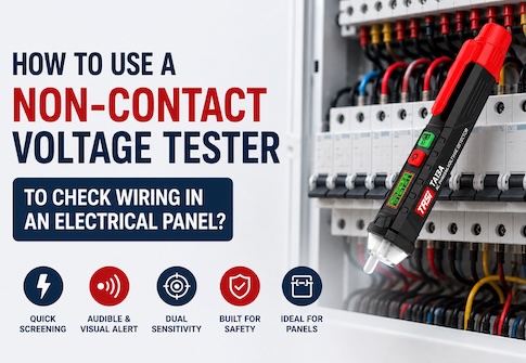
● Rapidly checking whether a power cable may be energized;
● Preliminary identification of an AC live conductor;
● Checking for voltage presence around an outlet;
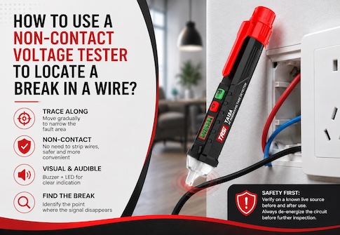
● Tracing the approximate location of a wiring interruption;
● Performing rapid screening before electrical maintenance.
The two types of tester operate on different principles and provide different kinds of information, so one should not automatically be considered a complete replacement for the other.
What Should Be Considered When Using an NCV Tester?
Understanding the construction of the tester is only part of using it correctly. Users should also understand its limitations.
● Before use, check the instrument according to the manufacturer's instructions and verify its response on a known energized source where appropriate;
● For safety-critical work, it may also be appropriate to recheck the tester on a known energized source after testing;
● Move the sensing area gradually toward the target rather than assuming that an indication from a long distance identifies one specific conductor;
● Adjacent energized wires may create electric-field coupling and cause an indication, particularly in densely wired areas;
● Metallic shielding, conductor depth, insulation thickness, and grounding conditions can reduce sensing performance;
● Most NCV testers are intended primarily for AC electric-field detection, and the supported voltage and frequency ranges should be confirmed from the specifications of the specific product;
● When confirming that a circuit is actually de-energized for safety-related work, follow the applicable electrical safety procedure and use the prescribed test method and equipment rather than relying solely on a single non-contact indication.
FAQ
What are the most important components of a non-contact voltage tester?
The sensing tip, sensing and signal-processing electronics, and indication system are the core components. The tip senses the AC electric field, the electronics process the signal, and the LEDs or buzzer communicate the result to the user.
Is there metal inside the sensing tip?
Many designs contain a conductive sensing electrode inside the tip, while the external surface is normally insulated. The exact internal construction depends on the product and should not be investigated by disassembling the tester.
How can an NCV tester detect voltage without touching the wire?
An energized AC conductor produces an alternating electric field. The tester detects this field through capacitive coupling, and its high-impedance electronics process the resulting weak signal.
Does the voltage shown by an NCV tester represent the actual circuit voltage?
Not necessarily. Many NCV testers indicate only the presence of an AC electric field, while some classify the detected signal into approximate voltage ranges. For an actual voltage value, use an instrument designed for direct voltage measurement.
Why do some NCV testers have high and low sensitivity settings?
Different sensitivity levels help adapt the tester to different environments. High sensitivity can detect weaker fields, while low sensitivity can reduce the sensing area and help distinguish between closely spaced conductors.
If the buzzer does not sound, is the circuit definitely de-energized?
No. Battery condition, test distance, shielding, insulation, instrument status, and environmental conditions can all affect the result. Safety-related absence-of-voltage verification should follow the applicable procedure and test method.
Can a non-contact voltage tester detect DC voltage?
Most conventional NCV testers are designed to detect alternating electric fields and are therefore intended mainly for AC circuits. Any additional detection capability must be confirmed from the specifications of the individual product.
Conclusion
Although a non-contact voltage tester is compact, it contains a complete electric-field sensing and electronic signal-processing system.
Typical components include the sensing tip, non-contact voltage-sensing circuit, amplification and filtering stage, control circuit, LED indicators, buzzer, function buttons, battery, and insulated housing. More advanced products may also provide a display, selectable sensitivity, LED flashlight, and automatic power-off.
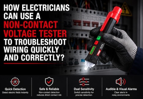
These components work together to detect an AC electric field, evaluate the signal, and provide an indication, making NCV testers useful for rapid preliminary screening during electrical inspection, maintenance, and troubleshooting.
At the same time, an NCV tester detects an electric field rather than establishing a direct electrical connection for precision voltage measurement. Understanding its construction and operating principle helps users apply the tool appropriately and avoid interpreting its indication beyond its intended purpose.